

Published on Apr 07, 2026
One of the most important issues for autonomous mobile Robots is their ability to navigate safely and reliably within their environments. Autonomous navigation can be defined as the ability of the robot to be able to answer these questions:
• What is the current location?
• How are the objects around me placed?
• How do I get to the destination?
We have tried to answer these questions by using an Optical Mouse for Odometry.
• The X and Y coordinates provided by mouse can be used to determine the distance and direction in which robot has traveled.
• The Mouse is attached to the body of the robot hence wheel slip and slides cannot affect the displacement measurement.
• By using a feedback control on the X coordinate the Robot can be made to move on a perfectly straight path thus replacing the need for stepper motors which are needed to maintain uniform speed in both left and right wheels.
• The coordinates provided by mouse are very precise with a least count of 0.25 mm.
• The obstacles in the path of the Robot can be avoided using IR transmitters and receivers.
Optical odometry is one in which the distance traveled is measured by optical means. Optical mouse consists of a single LED (Light Emitting Diode) which it bounces the light off the surface. It also has a very small camera which takes pictures of the surface. It scans the surface 1500 times a second. The digital signal processor receives the images that have been taken from the camera and analyses them for differences.
It can pick up very fine differences in the pictures and from this it can determine how far the mouse has moved across your desk and at what speed. Coordinates are then sent to the host. The DSP can detect patterns and analyze them at a very high speed. This is used for navigation.
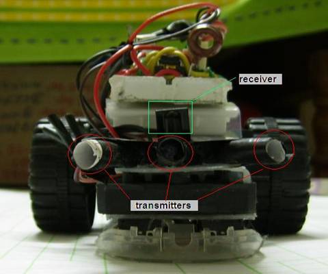
An obstacle map is created from the data received by the TSOP. Transmission signal consists of 7 bursts of IR signal, if more than 4 bursts are received by the TSOP then obstacle is present in the direction of the active transmitter. Thus activating the transmitters one after the other an obstacle map is created. From the obstacle map one can determine whether the obstacle is in-front of, to the left or to the right of the robot.
The receiver also receives the commands sent by TV remote. Different destinations can be selected by pressing specific keys on the TV remote. Signal is decoded by the microcontroller using Sony format (SIRCS).
