

Published on Aug 21, 2023
The goal of this project is to provide an emergency braking system which will stop the descent of the trolley automatically and allow for a manual, controlled descent to be performed by an occupant of the trolley if needed. The braking system must be reliable, be able to operate after long period of non-use and operate without destruction of major braking system components when used. The concept in which a brake calliper applies braking force directly to a secondary cable was selected. A provision for manual operation of the calliper is added to the system.
The trolley was intended to haul people and cargo up the steep slope to the building. The trolley operates on a single pull cable and at the inception of this project had no means of controlling the trolley should the pull cable break or the winch malfunction. An emergency braking system is required to keep people and cargo safe in the event of a cable or winch malfunction. The goal of this project is to provide an emergency braking system for the trolley that will activate automatically in the event of a cable or winch malfunction. The braking system will stop the descent of the trolley automatically and allow for a manual, controlled descent to be performed by an occupant of the trolley if needed. The braking system must be reliable, be able to operate after long periods of non-use, and operate without destruction of major braking system components when used.
An emergency braking system for a funicular trolley located is to be designed and prototyped. The braking system is to operate automatically in the event of a pull cable or winch gearbox malfunction. The braking system should either stop the trolley, or allow the trolley to descend to the bottom of the way at a controlled velocity of no more than 2 ft/sec. If the braking system is to stop the trolley, a provision for manual operation of the brake may be included to allow an occupant on the trolley to descend to the bottom of the trolley way. The braking system must be reliable, mechanical (non-electrical), and operate without the destruction of major braking system components. Documentation of the mechanism, including Bill of Materials (BOM), operating and maintenance instructions (O&M), and Assembly Drawings are to be delivered with the prototype
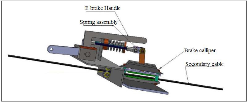
The product utilizes a secondary cable stretched from the top to the bottom of the trolley way. The secondary cable passes through a mechanical brake calliper which is attached to the trolley. A linkage set connects the winch pull cable to the calliper, and a spring is utilized to apply braking force to the calliper in the event of an emergency. Fig 1 provides models of the complete braking system. The braking system features three distinct subunits, the calliper assembly, the calliper activation assembly, and the cable guides. The internal search process produced feasible concepts.
These concepts fall into 3 basic categories: direct cable friction systems, brakes on a solid member, and brakes controlling the rotational motion of a shaft with rotation caused by an independent cable looped around a pulley connected to the shaft. The concept in which a brake calliper applies braking force directly to a secondary cable was selected. A provision for manual operation of the calliper by an occupant of the trolley was added to the system.
Sung-Min Moon , Jaemyung Huh , Daehie Hong, Seunghoon Lee c, Chang-Soo Hanc, in his paper, “Vertical motion control of building Façade maintenance robot with built-in guide rail (2014)” states that, “ Many researches on an automatic building façade maintenance system have been conducted to satisfy the increasing demands of façade maintenance. [1].
“Daniel blaire boren, Brett j Epstein, c. Hass, Hickman in his paper, “United States Patent (May 29,2001)” states that , “An apparatus for transporting a rider between two points on a Cable having a plurality of Supports Configured to suspend the cable or rope between two points of unequal elevation and a trolley [2]. Otterson et al., Gary Erickson, Smarte Trolleye, in his paper, “United States Patent (May 29, 2001)” [3] states that,” A nestable trolley, of the type guided by a walking attendant, for conveying a material such as luggage. The trolley has a frame and is supported by two rear wheels and a front rotatable caster.
The brake is automatically engaged when the trolley is left. [3]. Tretsiak, Dzmitry, Kliauzovich, Siarhei, in his paper, “Belarusian National Technical University, Belarus (2006)”,. State that “The current tendencies in automotive industry need intensive investigation in problems of interaction of active safety systems with brake system equipments.
The design team determined that the following requirements were highly important to the success of the concept:
Brake system will automatically stop the trolley (total combined weight < 800 lbs) in an emergency
The system should have a manual brake release on the trolley
Stopping acceleration will not be greater than the acceleration experienced at start up
All components must be mechanical
The braking system should capture the trolley to the track while still allowing for the trolley to be removed easily when necessary
The minimum factor of safety for all brake system components must be at least 2
System design mainly concerns with various physical constrains, deciding basic working principle, space requirements, arrangements of various components etc. Following parameters are looked upon in system design.
Selection of system based on physical constraints. The mechanical design has direct norms with the system design hence system is designed such that distinctions and dimensions thus obtained in mechanical design can be well fitted in to it.
Arrangement of various components made simple to utilize every possible space.
Ease of maintenance and servicing achieved by means of simplified layout that enables quick decision assembly of components.
Scope of future improvement.
In mechanical design the components are listed down and stored on the basis of their procurement in two categories,
Design parts
Parts to be purchased.
For designed parts detailed design is done and dimensions there obtained are compared to next dimensions which are already available in market. This simplifies the assembly as well as the post production and maintenance work. The various tolerances on work are specified .The process charts are prepared and passed to manufacturing stage. The parts to be purchased directly are selected from various catalogues and are specified so as to have case of procurement. Following are the various design components:
Design of input Shaft.
Design of output Shaft.
Design for Selection of Ball Bearing
Design of Load Drum Hub
Design of Screw
Brake Cable Failure Analysis
Testing of the E-barke system for trolley and cable to determine
1. Self-locking by proper selection and different pitch angles.
2. Mathematical model of dual worm system for optimal load lifting capacity, optimal factor of safety.
3. Derivation and resolution of system forces by drawing free body diagram of linkage.
4. Determination of forces and utilizing system of forces to determine the linkage dimensions of critical parts of drive.
[1] Surg min moon, Jaemging hue, Dachie Horg, Samghoon Lee, Chang sooltars, “Vertical motion contol of building façade maintance contact with built in guide rail ”,(Robotics and computer integrated manufacturing 31 (2014).
[2] Boren at.al,“ United state patend ”,( August, 7 2012 )
[3] Otterson et al.,“ United state patend ”,( August, 7 2012 )
[4] Andrew Diehl, Product development director of Holmer solution, “ Loads in zip STOP braking system”,(Zip STOP released may 2013).
