


Published on Aug 21, 2023
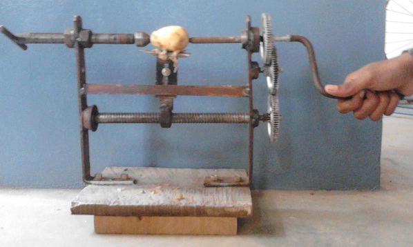
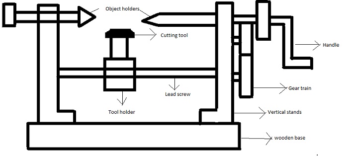
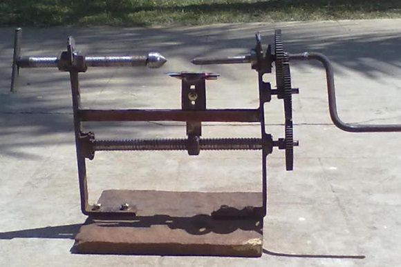
The need of present era is reusing of scrap or waste to prepare the useful products/items to the mankind/common man. Need of peeling fruits and vegetables using less human effort and less cost for household appliances lead to the design of manual peeling machine. The peeling machine is very useful for all food makers, small restaurants. This comprises of components like handle, gear train, bearings, lead screw, cutting tool and wooden base.
This paper discusses about making of manual peeling machine, understanding of theoretical and actual working principles of the peeling machine and its components for making the model by using scrap or reusable material. Here, all the components are assembled in a sequence order and they are fixed over the wooden base to prepare the working model. Also discussed about the characteristics of wood, advantages and disadvantages of lead screw.
Peeling of vegetables and fruits is one of the most frequent operations even at house hold purposes or at hotels. Manual peeling is peeling the vegetables with hand tool is toughest and time consuming process. It also causes for the loss of vitamins and become contaminated with the atmospheric air. This has led to the invention of a machine which peels the vegetables with less human effort and less time.
The Manual peeling machine uses a handle to rotate the job (vegetable to be cut eg .potato) and other side is fixed. A compound gear train is used to transmit the motion from handle to cutting tool through lead screw. The purpose of lead screw is to convert the rotary motion of the handle to linear motion. Ball bearings are used to avoid the frictional contact between two rotating parts wherever needed. As cutting tool is fabricated to the lead screw by some means the tool moves along the axis of the lead screw, so that peeling takes place. The whole setup is bolted to the wooden base.
There is a provision provided for changing the cutting tool depending upon the type of job used. Since the whole machine is made up of scrap material, it is cheaper and life of machine parts is more.
Handle
Gear train
Ball bearing
Lead screw
Wooden base
A handle is a part of, or attachment to, an object that can be moved or used by hand. The design of each type of handle involves substantial ergonomic issues, even where these are dealt with intuitively or by following tradition. Handle for tools is an important part of its function, enabling the user to exploit the tools to maximum effect.
The type of gear train used in manual peeling machine is compound gear train. A gear is a rotating machine part having cut teeth, or cogs, which mesh with another toothed part in order to transmit torque. Two or more gears working in tandem are called a transmission and can produce a mechanical advantage through a gear ratio and thus may be considered a simple machine. Geared devices can change the speed, torque, and direction of a power source. The most common situation is for a gear to mesh with another gear; however, a gear can also mesh with a non-rotating toothed part, called a rack, thereby producing translation instead of rotation. The gears in a transmission are analogous to the wheels in a pulley. An advantage of gears is that the teeth of a gear prevent slipping .When two gears of unequal number of teeth are combined, a mechanical advantage is produced, with both the rotational speeds and the torques of the two gears differing in a simple relationship.
Spur gears or straight-cut gears are the simplest type of gears. They consist of a cylinder or disk with the teeth projecting radially, and although they are not straight-sided in form, the edge of each tooth is straight and aligned parallel to the axis of rotation. These gears can be meshed together correctly only if they are fitted to parallel shafts.
A ball bearing is a type of rolling-element bearing that uses balls to maintain the separation between the bearing races. The purpose of a ball bearing is to reduce rotational friction and support radial and axial loads. It achieves this by using at least two races to contain the balls and transmit the loads through the balls. In most applications, one race is stationary and the other is attached to the rotating assembly (e.g., a hub or shaft). As one of the bearing races rotates it causes the balls to rotate as well. Because the balls are rolling they have a much lower coefficient of friction than if two flat surfaces were sliding against each other. Ball bearings tend to have lower load capacity for their size than other kinds of rolling-element bearings due to the smaller contact area between the balls and races. However, they can tolerate some misalignment of the inner and outer races.
An angular contact ball bearing uses axially asymmetric races. An axial load passes in a straight line through the bearing, whereas a radial load takes an oblique path that tends to separate the races axially. So the angle of contact on the inner race is the same as that on the outer race. Angular contact bearings better support "combined loads" (loading in both the radial and axial directions) and the contact angle of the bearing should be matched to the relative proportions of each. The larger the contact angle (typically in the range of 10 to 45 degrees), higher is the axial load supported, but lower is the radial load. In high speed applications, such as turbines, jet engines, and dentistry equipment, the centrifugal forces generated by the balls change the contact angle at the inner and outer race.
Ceramics such as silicon nitride are now regularly used in such applications due to their low density (40% of steel). These materials significantly reduce centrifugal force and function well in high temperature environments. They also tend to wear in a similar way to bearing steel—rather than cracking or shattering like glass or porcelain. Most bicycles use angular-contact bearings in the headsets because the forces on these bearings are in both the radial and axial direction.
The calculated life for a bearing is based on the load it carries and its operating speed. The industry standard usable bearing lifespan is inversely proportional to the bearing load cubed. Nominal maximum load of a bearing (as specified for example in SKF datasheets), is for a lifespan of 1 million rotations, at 50 Hz (i.e., 3000 RPM) is a lifespan of 5.5 working hours. 90% of bearings of that type have at least that lifespan and 50% of bearings have a lifespan of at least 5 times long. The industry standard life calculation is based upon the work of Lundberg and Palmgren performed in 1947. The formula assumes the life to be limited by metal fatigue and that the life distribution can be described by a Weibull distribution. Many variations of the formula exist that include factors for material properties, lubrication, and loading. Factoring for loading may be viewed as a tacit admission that modern materials demonstrate a different relationship between load and life than Lundberg and Palren proposed
Bearing life means how long you can expect your ball bearing to last under standard operating conditions. There will be a number of factors involved in the life of your bearing, including the amount of bearing load the ball bearing will be expected to handle. It is important to know the bearing life of your ball bearings so that you can plan down the road as to when you will have to replace your bearing.
Bearing life is calculated in terms of number of revolutions, so you will need to establish how much time a revolution takes and what percentage of time your application has the ball bearing in continuous revolution in order to determine your bearing life. The bearing life statistic is a measure of the amount of time in revolutions where 90% of the ball bearings can be expected to have survived. This does not mean every bearing will fail as soon as this number has been exceeded, of course.
The median life for ball bearings, also referred to as the Mean Time Before Failure, or MTBF, is about five times the basic life number for the bearing. This means that at 5 times the Basic Life Rating revolutions you should expect about half of your ball bearings to have failed. It is important to remember that there may be some variation in your individual results with a ball bearing and factors such as proper lubrication, care and handling of the bearing and stress on the bearing can result in very significant fluctuations in the life of the ball bearing.
In general, maximum load on a ball bearing is proportional to outer diameter of the bearing times width of bearing (where width is measured in direction of axle).
For a bearing to operate properly, it needs to be lubricated(by oil or grease). In most cases the lubricant is based on elasto hydro dynamic effect, but working at extreme temperatures. Dry lubricated bearings are also available. For a bearing to have its nominal lifespan at its nominal maximum load, it must be lubricated with a lubricant (oil or grease) that has at least the minimum dynamic viscosity recommended for that bearing. The recommended dynamic viscosity is inversely proportional to diameter of bearing. The recommended dynamic viscosity decreases with rotating frequency.
As a rough indication: for less than 3000 RPM, recommended viscosity increases with factor 6 for a factor 10 decrease in speed and for more than 3000 RPM, recommended viscosity decreases with factor 3 for a factor 10 increase in speed. For a bearing where average of outer diameter of bearing and diameter of axle hole is 50 mm and that is rotating at 3000 RPM, recommended dynamic viscosity is 12 mm²/s. Note that dynamic viscosity of oil varies strongly with temperature: a temperature increase of 50–70°C causes the viscosity to decrease by a factor 10.
Most bearings are meant for supporting loads perpendicular to axle ("radial loads"). Whether they can also bear axial loads, and if so, how much, depends on the type of bearing. Thrust bearings (commonly found on lazy susans) are specifically designed for axial loads For single-row deep-groove ball bearings, SKF's documentation says that maximum axial load is circa 50% of maximum radial load, but it also says that "light" and/or "small" bearings can take axial loads that are 25% of maximum radial load. For single-row edge-contact ball bearings, axial load can be circa 2 times maximum radial load, and for cone-bearings maximum axial load is between 1 and 2 times maximum radial load.
If both axial and radial loads are present, they can be added vectorially, to result in total load on bearing, which in combination with nominal maximum load can be used to predict lifespan. However, in order to correctly predict the rating life of ball bearings the ISO/TS 16281 should be used with the help of calculation software.
The part of a bearing that rotates (either axle hole or outer circumference) must be fixed, while for a part that does not rotate this is not necessary (so it can be allowed to slide). If a bearing is loaded axially, both sides must be fixed. If an axle has two bearings, and temperature varies, axle shrinks or expands, therefore it is not admissible for both bearings to be fixed on both their sides, since expansion of axle would exert axial forces that would destroy these bearings. Therefore, at least one of the bearings must be able to slide. A 'freely sliding fit' is one where there is at least a 4 μm clearance, presumably because surface-roughness of a surface made on a lathe is normally between 1.6 and 3.2 μm.
Bearings can withstand their maximum load only if the mating parts are properly sized. Bearing manufacturers supply tolerances for the fit of the shaft and the housing so that this can be achieved. The material and hardness may also be specified. Fittings that are not allowed to slip are made to diameters that prevent slipping and consequently the mating surfaces cannot be brought into position without force. For small bearings this is best done with a press because tapping with a hammer damages both bearing and shaft, while for large bearings the necessary forces are so great that there is no alternative to heating one part before fitting, so that thermal expansion allows a temporary sliding fit.
If a shaft is supported by two bearings and the center-lines of rotation of these bearings are not the same, then large forces are exerted on the bearing that may destroy it. Very small amount of misalignment is acceptable and how much depends on type of bearing. For bearings that are specifically made to be 'self-aligning', acceptable misalignment is between 1.5 and 3 degrees of arc. Bearings that are not designed to be self-aligning can accept misalignment of only 2–10 minutes of arc.
In general, ball bearings are used in most applications that involve moving parts. Some of these applications have specific features and requirements:
• Hard drive bearings used to be highly spherical, and were said to be the best spherical manufactured shapes, but this is no longer true, and more and more are being replaced with fluid bearings.
• German ball bearing factories were often a target of allied aerial bombings during World War II; such was the importance of the ball bearing to the German war industry.
• In horology, the company Jean Lassale designed a watch movement that used ball bearings to reduce the thickness of the movement. Using 0.20 mm balls, the Calibre 1200 was only 1.2 mm thick, which still is the thinnest mechanical watch movement.
• Aerospace bearings are used in many applications on commercial, private and military aircraft including pulleys, gearboxes and jet engine shafts. Materials include M50 tool steel (AMS6491), Carbon chrome steel (AMS6444), the corrosion resistant AMS5930, 440C stainless steel, silicon nitride (ceramic) and titanium carbide-coated 440C.
• Skateboarding. The wheels in a skateboard contain two bearings in each of the four wheels. Most commonly bearing 608-2Z is used (a deep groove ball bearing from series 60 with 8 mm bore diameter)
• Yo-Yos, there are ball bearings in the center of high quality Yo-Yos.
The advantages of a lead screw are:
Large load carrying capability
Compact
Simple to design
Easy to manufacture; no specialized machinery is required
Large mechanical advantage
Precise and accurate linear motion
Smooth, quiet, and low maintenance
Minimal number of parts
Capable of self-locking
The disadvantages are that most are not very efficient. Due to the low efficiency they cannot be used in continuous power transmission applications. They also have a high degree of friction on the threads, which can wear the threads out quickly. For square threads, the nut must be replaced; for trapezoidal threads, a split nut may be used to compensate for the wear.
The peeling machine consists of wooden- base lead-screw, gears, bearings, handle, stands, bolts and nuts. This machine construction is done by joining vertical stands with the help of bolts and nuts to the base. The lead-screw is joined to the two vertical stands including bearings. One side of vertical stand gives support to three gears. Upper gear is connected to one side of handle and another side is connected to the object holder. Another vertical stand is connected by nut and bolt mechanism to the object holder. The lead-screw supports the cutting tool with the help of hexagonal nut.
Working of manual peeling machine is, first we take the object (vegetable or fruit) and fitted into the object holders.The handle is rotated by applying human effort then the gear is rotated . The rotating gear is meshed up to another gear. The lead screw is connected to the meshed gear shaft .So the lead screw is rotated, the attached tool is moved linearly along the axis of the lead screw, thereby manual peeling is done.
1) 1 .Manual peeling machine is simplest and made by using scrap material with less cost.
2) 2. It is used for peeling different types of fruits, vegetables with less human effort and in less time. .It can be used easily for household purpose and hotels.
3) 3. It is portable for different types of cutting tools for peeling different types of fruits and vegetables.
4) 4. If all components of machine are made up of scrap then cost of material or parts is less.
K.Ch.sekhar, V.Jagadeesh, VSSR.Gupta, J.Kalpana
[1] Ikechukwu Celestine Ugwuoke, Olawale James Okegbile, Ibukun Blessing Ikechukwu, ” Design and Fabrication of Groundnut Shelling and Separating Machine”, International Journal of Engineering Science Invention, Volume 3, Issue 4, April 2014.
[2] Ikechukwu Celestine Ugwuoke, Olawale James Okegbile, Ibukun Blessing Ikechukwu,Robert Temitope John,” Design and Development of Manually Operated Roasted Groundnut Seeds Peeling Machine”, International Journal of Recent Development in Engineering and Technology, Volume 2, Issue 4, April 2014.
[3] Oladeji Akanni Ogunwole, “Design, Fabrication and Testing of A (Manually and ElectricallyOperated) Roasted Groundnut Decorticating Machine”, Food Science and Quality Managemen, Volume 14, 2013.
[4] Adetoro K. A,” Development of a yam peeling machine”, Global Advanced Research Journal of Engineering, Technology and Innovation ,Volume 1, July, 2012.
