

Published on Sep 03, 2023
In our project we are going to modify the present automatic gear shifting mechanism based on speed sensor in two wheelers. We are making an attempt to shift the gears in two wheelers (motor bikes) using pneumatics instead of foot lever operated systems. In the proposed system, the gear positions can be shifted by using pneumatic cylinders that can be placed near the gear pedal of the vehicle itself.
This enables easy shifting of the gears with the use of automatically it is connecting on speed sensor. It is speed sensing to when gear shifting level while automatically working on clutch it connecting also pneumatic cylinder.
When a gear shifting-up of an automatic transmission is to be effected, the load applied by the load device is increased, or the load is connected to an output rotation shaft of the engine via a selectively-connecting device, thereby reducing the rotational speed of the output rotation shaft of the engine to a required level. In our project, two pneumatic cylinders are coupled to the gear rod of the two ends and another think third pneumatic cylinder connecting to the clutch. The two levers are used to activate the pneumatic cylinders for forward and reverse position so that the gear will be shifted in speed sensor based and clutch also connecting micro controller.
At present due to the extended difficulties in manual operations, the technology has shifted from manual to automatic few of them include ABS system, active steering system etc.., in order to increase passenger safety and comfort. Increasing demands on performance, quality and cost are the main challenge for today’s automotive industry, in an environment where movement, component and every assembly operation must be immediately and automatically recorded, checked and documented for maximum efficiency. One of the automatic applications includes pneumatic gear changer. This study describes in detail in an understandable way to how to convert the traditional manually gear shifting mechanism by using microcontroller (control unit relays).
A method of controlling a gear change of an automobile, automobile comprising an internal combustion engine an automatic transmission connected to an output rotation shaft of engine so as to transmit the rotational output of engine to drive wheels of automobile through any selected one of a plurality of gear ratios a load device selectively connectable to output rotation shaft of engine via selectively-connecting means and means for generating a gear change control signal for selecting one of gear ratios of automatic transmission in accordance with one of operational conditions of automobile and engine method comprising the steps of controlling selectively-connecting means when gear change signal-generating means generates the control signal for shifting up the gear in automatic transmission, in such a manner that selectively-connecting means connects said load device to said output rotation shaft of said engine.
In our project we are doing automatic gear shifting for two wheeler in speed sensor based that is consider in speed level going to up position while will be increased that is time automatic clutch will be working that working condition in connecting pneumatic cylinder mechanism.
The speed will be going on reduced while gear will be reduced that is clutch also will be reduced condition that is condition working to the micro controller based.
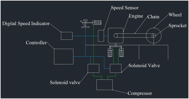
In this construction there are two pneumatic cylinders consisting of pistons on either side of the vehicle pedal for engaging the gear and another one cylinder connecting clutch lever.
The speed sensor connecting to the bike engine it is working microcontroller that is speed sensor sensing to the speed on bike engine in 10km/h (oscillation based) the solenoid valve on condition air will be going on air tube in pneumatic cylinder it is pulling to the gear rod when gear will be increased.
That is condition step by step speed increasing dependent on gear will be increase when time clutch lever will be pulling system it is also connecting pneumatic cylinder that is connecting on controller.
The same process in speed will be decreased when the time pneumatic cylinder off condition air will be going on another port it is gear will be reduced when the time clutch also pulling in used pneumatic cylinder.
The cylinders are operated with the help of a pressurized air coming from compressor and it is controlled by a control unit (micro controller).
This microcontroller (chip) is preprogrammed for working of the system. The role of two pneumatic cylinders is one for increasing the gear speed and for decreasing the gear speed. For the forward motion one cylinder is actuated & for the reverse motion second cylinder is actuated.
Three Single acting pneumatic cylinder connecting to the gear rod and clutch lever, the two cylinder connecting to the gear rod and another connecting to the clutch lever. That is cylinder connecting to the solenoid valve it working to the micro controller based on speed sensor.
• It requires simple maintenance.
• The safety system for automobile.
• Checking and cleaning are easy, because of the main parts are screwed.
• Easy to Handle.
• Low cost automation Project.
• Repairing is easy.
• Replacement of parts is easy.
• Should be used four wheeler and two wheeler
• It is additional cost is increased.
• It is extra space will be added.
