

Published on Apr 07, 2026
A brake is a mechanical device used in automobiles to inhibit the motion by absorbing kinetic energy of the moving system or body. Modern cars use the application of brakes on all four wheels for better performance and efficiency. This takes place with the help of Hydraulic brake system configuration circuits or dual circuits. The name dual circuit is so called, because each circuit acts on both front and rear wheels. These two circuits may be dependent or independent to each other in one or another way and as per the utility.
The paper throws some light on the utility of brake circuits that are currently being used in one or other way and some possible variations that can be inculcated for better performance and efficiency. Our main aim is to analyse the utility of different brake circuits for different terrains and vehicle design, and the factors that are involved during designing of the same. Further paper also investigates the effect of different dual circuits on the braking efficiency
Brakes in cars and trucks are safety parts. There is a major requirement of efficient braking not only in performance but also in comfort, maintenance and long working life. Optimum designing of today’s braking systems is found using additional calculations based on finite element analysis methods. Most brakes commonly use friction between two surfaces that arePressed together and convert the kinetic energy of the moving object into heat which can be dissipated or used in one or another form. The brakes may be drum type or disc type. There is a reason why disc brakes are used at front and drum brakes at rear in most cars. The stopping of vehicles results in more car weight at front tires and axles. An axle is a central shaft for a rotating wheel or gear.
Now since the disc brakes are more efficient and can bear more weight; they are used at front wheels Instead of conventional pattern and circuits, the four brakes can be of disc type for better performance and efficiency. Although because of the higher requirement of clamping forces, they are not generally used as parking brakes. This is one major reason why conventional brake circuits do not contain all brakes as disc type. Other minor Disadvantages of disc brakes include: not self-energizing, more noise production etc. In split or dual braking system, pressure to the brakes is applied to the wheels on separate lines carrying a special Hydraulic fluid.Most brake fluids generally used now a days or in day today automobile sector are glycol-ether based, however mineral oil and silicone (DOT 5) based fluids can also be used.
Brake fluids must meet certain norms and requirements as defined by various standards and organizations such asthe SAE, or local government authorities. This is done mainly for safety purpose. There are two basic types of split braking systems viz. a front and rear split system and the second is known as diagonal split braking system. There are different reasons for usage of both systems, but still they share the common goal of straight-line braking. These braking system works are based on hydraulic fluid that goes through rigid lines that apply pressure to the braking cylinders in the wheels, so a brake line failure may prove catastrophic. If the line leaks or breaks for any one or another reason, the pressure is permanently lost. Also if without pressure when the brake pedal is pressed, the braking cylinders in the wheels couldn't apply the necessary force needed to stop the wheels from spinning and, henceforth not able to stop the vehicle. This applies to both systems.
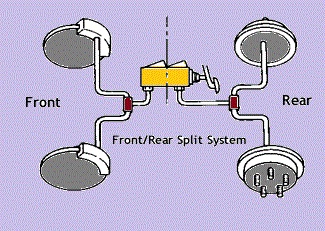
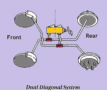
In few applications, the attainment of the rear brakes may be low enough that a completely failed front hydraulic circuit would not permit the vehicle to decelerate at an appreciable level. Therefore, an alternate hydraulic design that is the diagonal split, or X-split, connects the front and the diagonally opposed rear brake assembly (the left front brake and right rear brake, for instance) to each hydraulic circuit. In this manner, regardless of whichever hydraulic circuit fails, the remaining braking capacity of the system is the same. A hydraulic dual-circuit brake system with front or rear axle brake-circuit division comprises of an anti-lock system working on the recirculation principle. This takes place with the help of a device for driving dynamics control and another device for the automatic initiation of complete braking when the driver actuates the brake pedal.
An anti-lock braking system (ABS) for a road vehicle is comprised of a wheel slip control system (ASR) and a hydraulic dual circuit brake system equipped with front or rear axle brake static brake circuits, in which one brake circuit is allocated to the driven or rear wheels of the vehicle and one to the non-driven or front wheels [8]. The system includes two high-pressure pumps, each for the two brake circuits and which, in control stages of the ABS, brake fluid can be directly fed into the output pressure spaces of the brake unit where the high-pressure pump being allocated to the rear axle brake circuit can also be utilized as auxiliary pressure source for the ASR. At the front shaft brake circuit, the ABS operates on the feedback principle while at the rear shaft brake circuit it operates on the discharge or emission principle
Now the related work involves the individual pros and cons of different brake circuits and their requirements. The first and the simplest of all include Single line brake circuit. Two important requirements of the piping installation in this system are that the tubing must bear jerks and vibration and protected against corrosion. The disadvantage of using single line brake circuit lies in the fact that, if fuel leakage occurs then the entire hydraulically operated footbrake system can be rendered ineffective. To avoid this potential hazard, the brake system legislative requirements in Europe and the United States now demand a comparatively better and efficient braking system.
To eradicate the defects of Single line brake circuit, vehicles are now equipped with Divided line Brake Circuit. This is the only circuit in which different iterations can be performed. It includes front or rear split (already discussed), X split (or Diagonal split), L split and Triangular split. In the event of a tyre deflation or uneven braking, the wheel turning-in effect of negative offset tends to counteract any veering off course of the vehicle [10]. This feature is relevant to modern diagonal split dualcircuit safety braking system, since if either circuit misbehaves one front brake will develop much more drag force than the other. In X split circuit, each output from the Tandem Master cylinder supplies one front brake and its diagonally opposite rear brake, so that in the event of either line failing one-half of the normal maximum braking still remains available from one front and one rear wheel. In case of L split circuit, each output from the Tandem Master cylinder supplies one half of each front brake and a single rear brake. In the event of either line failing there is fewer imbalances of brakes than with the X split circuit.
A dual circuit brake valve includes first and second self-lapping valve elements for controlling primary and secondary fluid pressure braking circuits respectively, the first valve element is manually controlled and the second element is controlled by a relay piston that is subjected to the pressure in the primary circuit. The relay piston is subjected to the action of a pair of intermediate springs inopposite directions so that during operation of the first valve element the pressure required to open the second valve element is reduced to a minimum and the application of fluid pressure to the primary and secondary circuits is considerably simultaneous.
A dual brake valve used in a twin-circuit fluid pressure-operated vehicle braking system consists of a housing, two sets of ports, each containing an inlet and a delivery port, and also the two co-axial valve assemblies associated with the two sets of ports respectively, the valve assemblies each consisting of a poppet-type valve element, the head of which is subjected to delivery pressure.
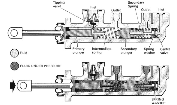
Pressureis also applied on an oppositely-directed face of the valve element in such a manner that fluid pressure across the valve element is balanced According to the design requirements, the return travel of secondary piston may be limited by a stop pin or screw. The operating chambers of the two pistons are supplied with fluid from an integral or separately attached reservoir, the latter being produced from a translucent plastic moulding to provide a ready visual indication of fluid levels. In both reservoir constructions an internal vertical baffle is used to preserve independence of fluid supply for each line of the divided brake circuit. When the brakes are applied in normal operation, the movement of the master cylinder push-rod urges the primary piston forwards.
This action closes the compensating port for the primary pressure chamber, either as a direct result of piston seal movement, or by piston movement allowing a tipping value to reseat. The ensuring rise in pressure ahead of the primary causes a similar forward movement of the secondary piston. This action likewise closes the compensating port for the secondary pressure chamber, either again as a direct result of piston seal movement, or by piston movement in this case allowing a centre valve to reseat. The same pressure is therefore generated ahead of both pistons and therefore in each line of the divided circuit.
In the event of pressure being lost in the line served by the primary piston, this piston will continue to move forwards until it contacts the secondary piston, thereby ensuring that pressure in the other line is maintained. Conversely, if pressure is lost in the line served by the secondary piston, the piston will move forward until it bottoms against the blind end of the cylinder, so that pressure growth between the primary and secondary pistons is still available in the other line. Clearly the travel of master cylinder push-rod will become greater whichever line of the divided circuit suffers loss of pressure, but in such an emergency it will still be capable of transmitting force to the piston serving the undamaged line and therefore actuate the respective brakes hydraulically
A dual-circuit pressure medium brake system comprises of special relay valves inclined ahead of the brake cylinders. Each brake circuit is equipped with a control also acting in the other circuit and covering each other, and the primary brake circuit is designed in such a way that it includes all such control elements necessary for adequate brake pressure adaptation, while a secondary brake circuit is simply an additional brake circuit without control elements. In this way each brake pressure metering can be simultaneously regulated. During the failure of the primary brake circuit, the secondarybrake circuit verifies a minimum brake pressure. This kind of pressure medium brake system is preferably used in air brake systems of motor vehicles [13].
A dual-circuit hydraulic brake system equipped with slip control mechanism, are provided with several sensors sensing the rotational behaviour of the wheels and several solenoid valves which can be controlled by slip monitoring electronics. The wheel brakes connected to the brake circuits can be pressurized by a tandem master cylinder, on the one hand, and by an auxiliary pressure source, on the other. The auxiliary pressure source consists of an electric-motor-driven pressure medium pump and of an accumulator. Each working chamber of the tandem master cylinder hydraulically communicates with a brake valve which may generate a dynamic pressure which, upon the actuation of the brake, will be supplied to wheel brakes by a switching-over action of inlet valves . The inlet valves are additionally regulated by a differential pressure alarm switch attached at the operating chambers of the tandem master cylinder. This prevents dynamic pressure medium from entering a defective brake circuit.
A hydraulic dual-circuit tandem main brake cylinder includes at least one closed brake circuit having a brake piston. This brake piston is activated by means of the pressure fed into a pressure chamber by means of a brake control valve along with a travel simulator spring. Adjoining this pressure chamber is also a supplementary piston device, which comprises an additional piston and a tappet passing there through and connected indirectly with the brake pedal. A highly progressive spring is connected between the additional piston and the tappet; this spring predominantly evaluates the pedal characteristic.
Wheel slip is selected as the controlled variable for braking control algorithms because it creates a strong influence on the braking force between the tire and the road. By controlling the wheel slip, we can regulate the braking force in order to obtain the required output from the system. In order to control thewheel slippage, we can frame system dynamic equations in terms of wheel slip.
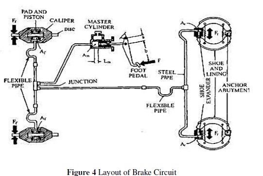
The force applied during braking of a vehicle restricts the motion of the wheels, as a result reduces the vehicle speed or brings it to a static position. Hence the braking force is the force of resistance applied to stop a vehicle or reduce its speed. To sum up, braking efficiency of a vehicle is defined as the braking force produced as a percentage of the total weight of the vehicle
![]()
For modern front-wheel-drive cars the X split circuit appears to have become an established practise, while the simple front-rear split circuit is still generally used on rear wheel drive cars. In off road vehicles usually ATVs or All-Terrain Vehicles, Y split circuit is used with the help of four disc brakes for efficient braking. This system is widely used nowadays in racing arena and SAEevents. Y split circuit is best suited for the ATVs or vehicles which do not involve the use of differential in the power train design. They either use Automatic locker or Spool and Mini spool in their transmission design.
From the visual representation and models developed in this paper, it was observed that relation between brake circuit and the utility of vehicle has a big influence on the performance of vehicle. It is better to use all brakes in the circuit as disc brakes if noise controlling can be done through noise absorbers. Further it was observed that unlike Single Brake line circuit, Dual or Divided Brake line circuit systems have provided a platform to work for different circuit and arrangements in order for optimization of vehicle performance. Further through mathematical formulae and calculations, it has been observed that the percentage of wheel slippage varies inversely with the deceleration of the vehicle and also the ease of steering
Priyesh Jain, Hitesh Garani
[1] Hohmann, C., et al. "Contact analysis for drum brakes and disk brakes using ADINA." Computers & structures 72.1 (1999): 185-198.
[2] Wikipedia contributors. "Brake." Wikipedia, The Free Encyclopedia. Wikipedia, The Free Encyclopedia, 10 Oct. 2016. Web. 10 Oct. 2016.
[3] Wikipedia contributors. "Axle." Wikipedia, The Free Encyclopedia. Wikipedia, The Free Encyclopedia, 21 Sep. 2016. Web. 21 Sep. 2016
[4] Ayers CAyers C. What Is a Split Braking System? | eHow. eHow. 2016. Available at: http://www.ehow.com/about_6545035_split-braking-system_.html. Accessed October 18, 2016.
