


Published on Apr 07, 2026
The various machining process in manufacturing industries are carried out by separate machining machine. It need more space requirement and time with high expenses. But the fabrication of multi operation machine, which contains three operations in a single machine. The operations are namely drilling, slotting and shaping. It is a new concept specially meant to reduce the work time and save the cost. Instead of using a slotting machine we are using the special arrangements for slotting operation in the drilling machine same for the shaping operation also, so we can save the investment cost of exceed slotting and shaping machine in the industries.
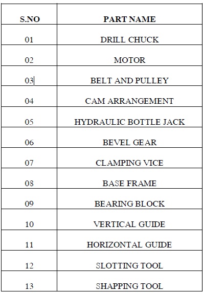
The machine operates through drilling machine with the bevel gear and cam mechanism arrangements. Hence exactly we can carry out three operations in this machine, namely drilling, slotting and shaping. It is a simple in construction and easy to operate. Driller, Bevel gear, Drill bit, Chuck, Cam mechanism, bearings, slotting tool, shaping tool and guide are the main parts used in this machine.
The multi process machine is used to do the multi operations like Drilling, Shaping, Slotting at a time and which is used to save the time and space requirement of an industry. The main concept of machine is to do the operations like slotting and shaping by the use of drilling operation using cam arrangement.
A drill is a tool fitted with a cutting tool attachment, usually a drill bit used for drilling holes in various materials or fastening various materials together with the use of fasteners. The attachment is gripped by a chuck at one end of the drill and rotated while pressed against the target material. The tip of the cutting tool does the work of cutting into the target material. Drills are commonly used in woodworking, metalworking and construction. Specially designed drills are also used in medicine, space missions and other applications. Drills are available with a wide variety of performance characteristics, such as power and capacity.
Shaper operates by moving a hardened cutting tool backwards and forwards across the workpiece. On the return stroke of the ram the tool is lifted clear of the workpiece, reducing the cutting action to one direction only. The workpiece mounts on a rigid, box shaped table in front of the machine. The height of the table can be adjusted to suit this workpiece, and the table can transverse sideways underneath the reciprocating tool which is mounted on the ram, the table motion is usually under the control of an automatic feed mechanism which acts on the feedscrew. The ram slides back and forth above the work, at the front end of the ram is a vertical tool slide that may be adjusted to either side of the vertical plane. This tool slide holds the clapper box and toolpost from where the tool can be positioned to cut the straight, flat surface on the top of the workpiece. The tool slide permits feeding the tool downwards to put on a cut it or may be set away from the vertical plane, as required. The ram is adjustable for stroke and due to the geometry of the linkage, it moves faster on the return stroke than on the forward, cutting stroke. This action is via a slotted link or whit worth link.
A cam is a rotating or sliding piece in a mechanical linkage used especially in transforming rotary motion into linear motion or vice-versa. It is often a part of a rotating wheel (e.g. an eccentric wheel) or shaft (e.g. a cylinder with an irregular shape) that strikes a lever at one or more points on its circular path. The cam can be a simple tooth, as is used to deliver pulses of power to a steam hammer, for example, or an eccentric disc or other shape that produces a smooth reciprocating (back and forth) motion in the follower, which is a lever making contact with the cam. The cam can be seen as a device that rotates from circular to reciprocating (or sometimes oscillating) motion. A common example is the camshaft of an automobile, which takes the rotary motion of the engine and translates it into the reciprocating motion necessary to operate the intake and exhaust valves of the cylinders. Cams can also be viewed as information-storing and transmitting devices. Examples are the cam-drums that direct the notes of a musical box or the movements of a screw machine's various tools and chucks. The information stored and transmitted by the cam.
A bevel gear is a type of mechanical gear. These gears where the axes of the two shafts intersect and the tooth bearing faces of the gears themselves are conically shaped. Bevel gears are most often mounted on shafts that are 90 degrees apart, but can be designed to work at other angles as well. The pitch surface of bevel gears is a cone.
Bottle jacks are hydraulic jacks that are placed in a horizontal position. These jacks push against a lever, which lifts the main lift arm. Bottle jacks have a longer handle than most hydraulic jacks, however, and it is possible to get more lift per stroke with the increased leverage they provide when compared to regular models of jacks. Bottle jacks are versatile because their horizontal position makes it possible to place them in tight spots and provides good leverage. Recently bottle jacks have proven useful in search and rescue missions following earthquake damage. As a result, bottle jacks are standard equipment in firehouses and for search and rescue teams. They are also used for lifting, spreading, bending, pushing, pressing, or straightening requirements. The base and cylinders of bottle jacks are electrically welded for strength, and all models are capable of working in upright, angled, or horizontal positions.
It is a device consisting of two parallel jaws for holding a work piece; one of the jaws is fixed and the other movable by a screw, a lever, or a cam. When used for holding a work piece during hand operations, such as filing, hammering, or sawing, the vise may be permanently bolted to a bench. In vises designed to hold metallic work pieces, the active faces of the jaws are hardened steel plates, often removable, with serrations that grip the work piece; to prevent damage to soft parts, the permanent jaws can be covered with temporary jaws made from sheet copper or leather.
Pipe vises have double V-shaped jaws that grip in four places instead of only two. Woodworking vises have smooth jaws, often of wood, and rely on friction alone rather than on serrations. For holding work pieces on the tables of machine tools, vises with smooth hardened-steel jaws and flat bases are used. These machine vises are portable but may be clamped to the machine table when in use; means may also be provided for swiveling the active part of the vise so that the work piece can be held in a variety of positions relative to the base. For holding parts that cannot be clamped with flat jaws, special jaws can be provided.
A bearing is a device to permit constrained relative motion between two parts, typically rotation or linear movement. Bearings may be classified broadly according to the motions they allow and according to their principle of operation. Low friction bearings are often important for efficiency, to reduce wear and to facilitate high speeds. Essentially, a bearing can reduce friction by virtue of its shape, by its material, or by introducing and containing a fluid between surfaces. By shape, gains advantage usually by using spheres or rollers. By material, exploits the nature of the bearing material used.
Sliding bearings, usually called bushes bushings journal bearings sleeve bearings rifle bearings or plain bearings. rolling-element bearings such as ball bearings and roller bearings. Jewel bearings, in which the load is carried by rolling the axle slightly off-center. fluid bearings, in which the load is carried by a gas or liquid magnetic bearings, in which the load is carried by a magnetic field. Flexure bearings, in which the motion is supported by a load element which bends. Bearings vary greatly over the forces and speeds that they can support.
Forces can be radial, axial (thrust bearings) or moments perpendicular to the main axis. Bearings very typically involve some degree of relative movement between surfaces, and different types have limits as to the maximum relative surface speeds they can handle, and this can be specified as a speed in ft/s or m/s. The moving parts there is considerable overlap between capabilities, but plain bearings can generally handle the lowest speeds while rolling element bearings are faster, hydrostatic bearings faster still, followed by gas bearings and finally magnetic bearings which have no known upper speed limit.
Drilling tool is a cylindrical end-cutting tool used to originate or enlarge circular holes in solid material. Usually, drills are rotated by a drilling machine and fed into stationary work, but on other types of machines a stationary drill may be fed into rotating work or drill and work may rotate in opposite directions. To form the two cutting edges and to permit the admission of a coolant and the ejection of chips, two longitudinal or helical grooves or flutes are provided. The point or tip, of a drill is usually conical in shape, and it has cutting edges where the flutes end. The angle formed by the tapering sides of the point determines how large a chip is taken off with each rotation of the drill. The degree of twist of the helical flutes also affects the drill’s cutting and chip-removal properties.
For general purpose twist drills the helix angle is about 32°. The angle formed by the two sides of the tapering point is 118° for standard drills, while for drilling tough metals, a flatter point with a 135° angle is recommended. The peripheral portion of the drill body not cut away by the flutes is called the land, and to reduce friction and prevent the land from rubbing against the sides of the hole, most of the land is cut away, leaving a narrow ridge called the margin that follows the edge of the side of the flute that forms the cutting edge.
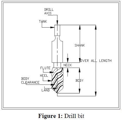
The fluted part, or body, of a drill is either hardened high-carbon steel or high-speed steel; other drills have inserts of cemented carbide to form cutting edges or are made from sintered-carbide rods. The shanks of twist drills are either straight or tapered and when not integral with the body are made from low-carbon steel and welded to the body.
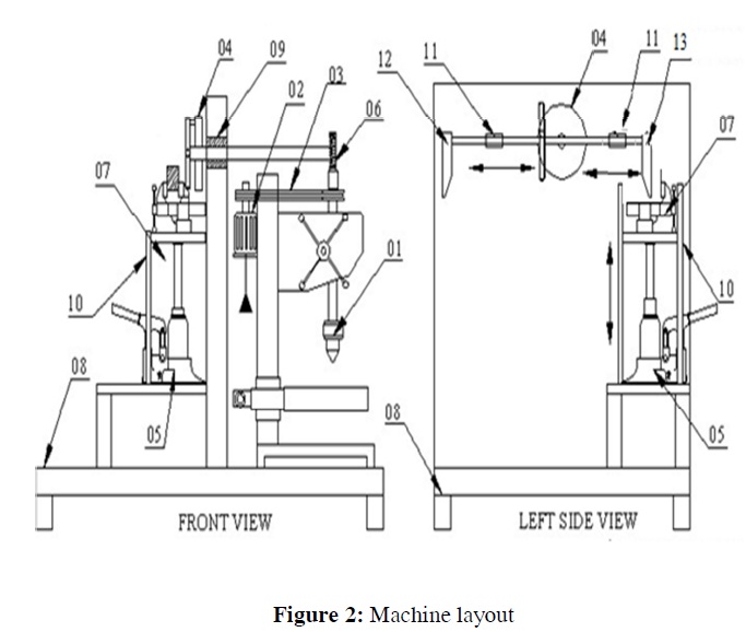
Here the bevel gear arrangement is used for carrying out the operations. Bevel gear is used to perpendicular (90) power transmission. One of the bevel gear is connected with the motor and another one with the drill chuck hence when the motor is rotated the drill chuck also rotates. The motor pulley shaft is connected to a cam arrangement on the other side. Cam arrangement converts rotary motion into reciprocating motion and the reciprocating motion is used for the slotting and shaping operation. The slotting toll and shaping tool are guided by a horizontal guide bush.
The up down table is mounted on a hydraulic bottle jack piston rod hence when the bottle jack handle is pumped the table height can be adjusted according to the requirement when the after the process is completed the pressure should be released through pressure relief valve to make the table come down. A vice is mounted on the table to hold the work piece.
a. Easy to operate.
b. Reduces time and increases production rate.
c. Low maintenance.
d. Easy to implement
a. Used in small scale industries to reduce machine cost.
b. In such places where frequent change in operation are required.
The project carried out by us made an impressing task in the field of industrial and automated workshops. It is very usefully for the workers to work in the industrial workshop are in the service station. This project has also reduced the cost involved in the concern. Project has been designed to perform the entire requirement task which has also been provided.
1. Bosetti, P., Leonesio, M. and Parenti, P. (2013) ‘On development of an optimal control system for realtime process optimization on milling machine tools’ 8th CIRP Conference on Intelligent Computation in Manufacturing Engineering, pp. 31 – 36.
2. Jonghyuck Park, Ick-Hyun Kwon, Sung-Shick Kim and Jun-Geol Baek (2011) ‘Spline regression based feature extraction for semiconductor process fault detection using support vector machine’ Expert Systems with Applications, pp.5711–5718.
3. Liang Quan, Wang Yongzhang, Fu Hongya and Han Zhenyu (2008) ‘Cutting Path Planning for Ruled Surface Impellers’ Journal of Aeronautics, pp.462-471.
4. Liu Huran (2011) ‘The realization of the “SFM” and “HFM” method on the CNC hypoid cutting machine’ Procedia Engineering, pp. 729 – 733.
