

Published on Apr 07, 2026
This paper describes the design and analyses of a single seater race car chassis frame, according to the specifications of 2014 Formula SAE rule book. The work focuses on the important design parameters around the driver instead of designing the car and the quantitative predictions of different dimensions and mechanical parameters, using the given information and relevant approximations. Design model was prepared using anthropometric parameters of tallest driver as 95th percentile male was selected to SAE rules book.
In this description CATIAV5, HYPERMESH, ANSYS14.5 software's are utilized in order to design and analysis the chassis frame. Based on this design part deformation occurred on the chassis frame at different load conditions and Stress distribution along the each element can be determined.
Formula SAE is an understudy rivalry, supported by the Society of Automotive Engineers (SAE), in which understudies plan, fabricate, and complete with a little equation style race auto. The FSAE rivalry was made to give an instructive experience to school understudies that are practically equivalent to the sort of undertakings they will confront in the work energy. The opposition likewise incorporates some static plan occasions, where the expense and outline of the auto is judged by a board. A chassis is the component in a car that everything else attaches to. The most basic, common chassis design is referred to as the “Ladder Frame” due to its resemblance to a conventional lean-to ladder (Adams, 1992). A “Ladder Frame” consists of two long members that run the length of the automobile and are joined by a set of smaller member perpendicular to the two long members.
The other components that make up the vehicle are then mounted to this chassis. In the case of the Ladder Frame, the body and engine are usually mounted to the top of the chassis with the suspension being mounted below. In more recent times the chassis has evolved and in some cars it can be hard to distinguish between what makes up the body of a vehicle and what makes up the chassis. A monologue chassis uses the body as the load carrying component and means that no separate chassis structure is needed. Entire panels carry the load rather than specific members, often these panels are the outermost parts of the body which means that a higher polar moment of Inertia (about the axis running from the front to the rear of the car) is achievable.
Chassis is a fabricated structural assembly that supports all functional vehicle systems. This assembly may be a single welded structure, multiple welded structures or a combination of composite and welded structures .The first step to designing a chassis is to understand the various loads acting on the structure.
The main deformation modes occurring on the chassis is as follows
i. Longitudinal Torsion
ii. Vertical Bending
iii. Lateral Bending
iv. Horizontal Lozenging
At the point when the connected burdens following up on one or two oppositely contradicted corners of the auto torsion happens. This will encounter while moving an auto on street subjected to compels of distinctive sizes. The edge could be thought as a torsion spring interfacing the two finishes where suspension burdens act. Torsional stacking and undesirable redirections of suspension springs can influence the taking care of and additionally execution of the auto. The imperviousness to tensional misshapening is called solidness spoke to in name. In the execution of a FSAE race auto this is the essential determinant.
In this case the frame is act as a simply supported beam and the four wheels as supports and the weight of the driver and components mounted to the frame, such as the engine and other parts are acting at the centre of the frame. Under the effect of gravity produce sag in the frame. Hence the vertical damping force due acceleration or deceleration can increase the vertical deflections.
Lateral bending loads are induced in the frame for various reasons, such as road camber, side wind loads and centrifugal forces caused by cornering. The sideways forces will act along the length of the car and will be resisted by the axles, tires and structural members.
This deformation is caused when the forward and backward forces applied at opposite wheels. These forces tend to distort the frame into a parallelogram shape. If torsional and vertical bending stiffness are satisfactory, then the structure will generally be satisfactory. The magnitude of these load changes with the operating mode of the car.
The design of the chassis must work around a number of parameters and constraints in order for it to perform well and for it to be eligible to compete in the competition. These requirements can be broken into several categories which will be discussed below. If any of these requirements are not met, the consequences range from sub-optimal performance to not being eligible to compete in the competition or even chassis failure. So it is clear that all requirements must be carefully considered and even re-visited when designing and building the chassis.
The first thing that must be considered when designing the chassis is the 2014 FSAE rules, there is no point in designing a chassis if it will not be allowed to compete in the competition for which it is designed. The FSAE rules require a front and rear roll hoop, a side impact structure, a front bulkhead and supports for the aforementioned components be integrated into the chassis. By representing graphically these 12 requirements one may create a “minimum chassis’ Figure 1 which shows the simplest possible configuration of members that include the required components mentioned above. Figure 2 is a side view diagram of what this “minimum chassis” looks like, it does not consider driver ergonomics, cockpit entry or suspension points etc, and is merely a pictorial representation of some of the required members.
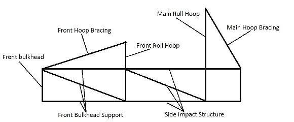
The FSAE rules define a minimum size for all the chassis members shown in Figure 2 and for some other members not shown. To avoid adding un-necessary weight, the chassis design should make best use of the required members so that as few possible additional members are needed. This is where much of the design work needs to be done for the project because as the rules limit many of the members, little design work can be done in optimizing the size of the chassis members.
The FSAE rules also require a firewall barrier to isolate the batteries from the driver, it must cover the vertical and horizontal portions of the battery box that face the driver. 2.6mm aluminium sheet is suggested for this firewall but 1mm steel has been approved as an alternative by the FSAE-A rules committee. The chassis must also provide sufficient space for cockpit entry, where the driver enters the cockpit. FSAE rules require a template shown in Figure 4 be able to pass vertically through the cockpit opening until it reaches the height of the top bar in the side impact structure.
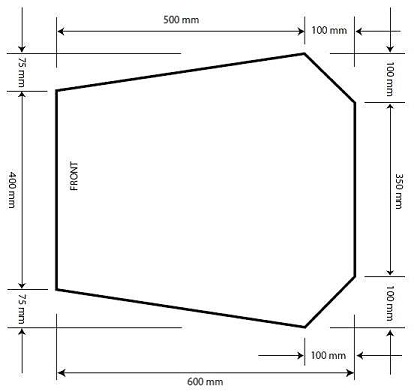
A sufficiently large foot-well area must also be present in the chassis for the driver’s legs and feet. The foot-well is the area where the accelerator and brake pedals are located and is where the driver’s legs lie when driving. The foot-well area lies between the front suspension pivots so the design will have to work around this area carefully so that the suspension loads are adequately supported, to avoid damaging the chassis and potentially injuring the driver. Fig 4 shows the template that must be able to pass horizontally through the footwell according to the FSAE rules.
A space frame is designed in several steps that are based on the design considerations. A methodical plan must be followed so that all parameters are considered and the design incorporates every part of the car correctly. The chassis wire frame model is designed by using CATIA V5R20 Generative Shape Design Tool. Initial Setup – First, baseline dimensions like wheelbase, overall length, width, and height were selected. Stemming from these dimensions were roll hoop locations, bulkhead location, engine mounting location, and wheel centrelines. Once these dimensions were selected, a series of planes were created in CATIA V5 at these points so that these locations could be visualized.
Fixed elements include roll hoops, front bulkhead, suspension points, and engine mounts. These features will not be moved around during chassis wire frame design iteration so that the number of variables able to be manipulated may be decreased. This allows for a quicker design period so that construction may begin sooner than usual.
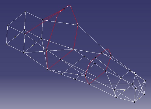
Altair Hyper Mesh is a high-performance finite element pre-processor that provides a highly interactive and visual environment to analyze product design performance. There are two methods of mesh refinement. H-refinement- refers to the process of increasing the number of elements used to model a given domain, consequently, reducing individual element size. p-refinement- element size is unchanged but the order of the polynomials used as interpolation functions is increased. Steps to be followed to do 1-D mesh
· Import the Chassis wire frame model into the Hypermesh.
· Connect all the lines of the chassis frame.
· Create two components and move the lines into the components by using organise tool bar (because the chassis frame having two variable cross sections).
· create a 1D line mesh (Beam188,element size 10).
· Check the connectivity of the elements.
· Correct the free 1D elements.
· Export the meshed model to the Ansys.
The Finite Element Analysis (FEA) is a numerical method for solving problems of manufacturing and mathematical physics. Design geometry is a lot more difficult and the accuracy requirement is a lot higher.
We require
– To understand the physical behaviours of a complex entity (strength, heat transfer capability, fluid flow, etc.)
– To predict the performance and behaviour of the design.
– To calculate the safety margin.
– To identify the limitation of the design perfectly.
– To identify the optimal design with confidence.
In this project it is concluded that the chassis frame is with stands for four types of loading conditions and satisfying the FSAE rules and constrains. Thus would conclude by observing the above results and analyzation that the chassis space frame structure depend on the stiffness and stresses in that particular frame. The stresses obtained above are the well deserved in order to manufacture a chassis space frame as the stresses are very much lower as compared to that of the yield point of the material.
1. 2014 Formula SAE® Rules, SAE International, USA.
2. M A Abdullah titled with "Development of formula varsity race car chassis "2nd International Conference on Mechanical Engineering Research(ICMER2013) IOP Publishing.
3. Ravinder Pal Singh titled with " structural performance analysis of formula sae car" Jurnal Mekanikal, December 2010
4. Mohd Azman. Abdullah titled with " Design, Analysis and Fabrication of Chassis Frame for UTeM Formula Varsity TM Race Car" International Journal of Mining, Metallurgy & Mechanical Engineering (IJMMME) Volume 1, Issue 1 (2013) ISSN 2320–4060.
