


Published on Apr 07, 2026
The bending machine is one of the most important machine tool in sheet metal work shop. It is primarily designed for bending. The bend has been made with the help of punch which exerts large force on the work clamped on the die. The bending machine is designed in such a way that, it works automatically. The automation strategy, when implemented is believed to result in reduced cycle time, costs and improved product quality. Other possible advantages are repeatability, increased productivity, reduced labor and integration of business systems. Automation is achieved with the help of Electro pneumatic system.
Now a day in industries especially in automobile and other industries the automatic plate bending machines are widely used. Earlier the bending machines where operated manually. So the output of machine was very less. Because the movement of ram was done manually by rotating the screw. Now the technique of bending operation of the component is changed. Once the plate is loaded the operator should not only use once push button to start the machine. But he has operated two push buttons so that both the hands of the operator are engaged. This arrangement is made in order to avoid injuries to operators.
The main aim of this project is to have the complete know how of pneumatic devices, sensors etc. by which the manually operated press or any machine can be converted into a semi or fully automatic unit. In this project the bending machine is a semi-automatic bending machine, in which the loading and unloading of the component is done manually and the bending of the plate is done automatically
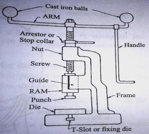
A general definition of the word “Press”, as used for the purposes with which we are concerned in this treatise, might be written as follows: A machine in which a bed or anvil is approached by a ram or hammer, having a reciprocating motion in a line approximately at right angles to said bed, and the said ram being suitably guided in the frame work of the machine so that it may always move in the same path. It will thus be seen that the two important members in any ordinary press are the bed and the ram, and that they are only a more highly specialized form of the Black Smith’s anvil and hammer or of the still more primitive large stone and small stone used by the predecessors.
1.Pneumatic Cylinder:-
• Pneumatic cylinders come in many basic versions.
• All cylinders can be tweaked to better fit an application
. • Custom designs can perform better and save money when standard cylinders don’t fit the job.
Pneumatic cylinders are widely used to generate force and motion on a vast range of OEM equipment. They can move products directly or indirectly by pushing, pulling, lifting, lowering, or rotating, and can keep them from moving by clamping them in place. Wide acceptance comes in large part because cylinders are simple, economical, durable, and easy to install. They can produce thousands of pounds of force over a broad range of velocities; cycle at high speeds without overheating; and stall without internal damage. And they readily tolerate tough conditions such as high humidity, dusty environments, and repetitive high-pressure wash downs. Pneumatic actuators come in literally thousands of styles, sizes, and configurations. This variety makes more innovative-equipment possible, but sorting out the best cylinder for an application can be a bit overwhelming. Here are some key considerations.
The basic, rod-style industrial cylinder consists of a tube sealed by end caps. A rod attached to an internal piston extends through a sealed opening in one of the ends. The cylinder mounts to a machine and the piston rod acts upon the load. A port at one end of the cylinder supplies compressed air to one side of the piston, causing it (and the piston rod) to move. The port at the other end lets air on the opposite side of the piston escape —usually to atmosphere. Reversing the roles of the two ports makes the piston and rod stroke in the opposite direction. Rod-style cylinders function in two ways:
Double-acting cylinders use compressed air to power both the extend and retract strokes, moving the rod back and forth. This arrangement makes them ideal for pushing and pulling loads. Controlling the rate at which air exhausts determines rod speed.
Single-acting cylinders have compressed air supplied to only one side of the piston; the other side vents to atmosphere. Depending on whether air is routed to the cap or rod end determines whether the rod extends or retracts.
Repairable cylinders can be disassembled to replace seals and other internal components. This extends a cylinder’s life. These durable cylinders are generally used in rugged, heavy-duty applications. Sealed-for-life or “disposable” cylinders have end caps mechanically crimped to the tube. Internal components are preluded prior to assembly. Although they are less expensive to manufacture than comparable repairable cylinders, they cannot be taken apart to repair without destroying the housing. These cylinders are usually used in lighter-duty applications and must be replaced when they fail.
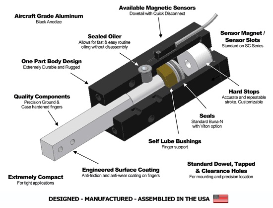
Cylinders fit into smaller spaces where only a short stroke is required. They are used in lighter-duty applications due to the small bearing surface on which the rod slides. They mainly come in single-acting versions, but double-acting styles also are available.
Cylinders have guide rods and guide blocks mounted parallel to the piston rod, or dual piston rods. They prevent the piston from rotating and provide precise, controlled linear motion —especially when the unit is subject to high side loads. In such cases, the guides reduce rod and piston bending and uneven seal wear. They are recommended in applications with sizeable offset loads or require that the load be guided, for example, down a conveyor.
Units convert a cylinder’s linear motion to angular rotation that can exceed 360°. The rotary actuators —with the rack mounted on the rod —are often used in process industries to operate quarter-turn valves.In addition to rod-type cylinders, other designs included.
Are durable, single-acting actuators with flexible, reinforced-elastomeric walls and metal end plates. They extend when inflated and can generate high forces, thanks to their large diameters. A cylindrical shape lets them bend in any direction, making them useful where load direction might curve. Note that external restraints should be used to limit maximum extension and compression. Unrestrained extension can blow off the end plate, and exhaust without restraint can let the load crush the sidewalls. Rodless cylinders, as the name implies, have no rod extending through the end caps. Instead, an external carriage slides back and forth on the tube. The load mounts on this carriage. In many designs, an internal piston is mechanically connected to the carriage through a sealed longitudinal slot in the cylinder wall. Long sealing strips inside and outside the cylinder tube prevent air leaks and dust and dirt ingression. Other variations include cable-and-pulley arrangements and magnetically coupled pistons and carriages.
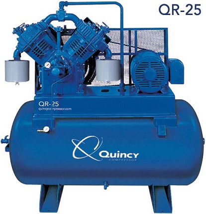
Positive-displacement compressors work by forcing air into a chamber whose volume is decreased to compress the air. Common types of positive displacement compressors are:-
• Piston-type air compressors use this principle by pumping air into an air chamber through the use of the constant motion of pistons. They use one-way valves to guide air into a cylinder chamber, where the air is compressed. Rotary screw compressors use positive-displacement compression by matching two helical screws that, when turned, guide air into a chamber, whose volume is decreased as the screws turn.
• Vane compressors use a slotted rotor with varied blade placement to guide air into a chamber and compress the volume. A type of compressor that delivers a fixed volume of air at high pressures.
Negative-displacement air compressors include centrifugal compressors. These use centrifugal force generated by a spinning impeller to accelerate and then decelerate captured air, which pressurizes it.
• To supply high-pressure clean air to fill gas cylinders
• To supply moderate-pressure clean air to a submerged surface supplied diver
• To supply moderate-pressure clean air for driving some office and school building pneumatic HVAC control system valves
• To supply a large amount of moderate-pressure air to power pneumatic tools, such as jackhammers
• For filling tires
• To produce large volumes of moderate-pressure air for large-scale industrial processes (such as oxidation for petroleum coking or cement plant bag house purge systems).
Forming dies are typically made by tool and die makers and put into production after mounting into a press. The die is a metal block that is used for forming materials like sheet metal and plastic. For the vacuum forming of plastic sheet only a single form is used, typically to form transparent plastic containers (called blister) for merchandise. Vacuum forming is considered a simple molding thermoforming process but uses the same principles as die forming. For the forming of sheet metal, such as automobile body parts, two parts may be used: one, called the punch, performs the stretching, bending, and/or blanking operation, while another part, called the die block, securely clamps the work piece and provides similar stretching, bending, and/or blanking operation.
The work piece may pass through several stages using different tools or operations to obtain the final form. In the case of an automotive component there will usually be a shearing operation after the main forming is done and then additional crimping or rolling operations to ensure that all sharp edges are hidden and to add rigidity to the panel. Die components:- The main components for die toolsets are:
• Die block - This is the main part that all the other parts are attached to.
• Punch plate - This part holds and supports the different punches in place.
• Blank punch - This part along with the blank die produces the blanked part.
• Pierce punch - This part along with the pierce die removes parts from the blanked finished part.
• Stripper plate - This is used to hold the material down on the blank/pierce die and strip the material off the punches.
• Pilot - This is used to keep the material being worked on in position.
• Guide, back gage, or finger stop - These parts are all used to make sure that the material being worked on always goes in the same position, within the die, as the last one.
• Setting (stop) block - This part is used to control the depth that the punch goes into the die.
• Blanking dies - See blanking punch
• Pierce die - See pierce punch.
• Shank - used to hold in the presses. it should be aligned and situated at the center of gravity of the plate.
A blanking die produces a flat piece of material by cutting the desired shape in one operation. The finish part is referred to as a blank. Generally a blanking die may only cut the outside contour of a part, often used for parts with no internal features. Three benefits to die blanking are:
1. Accuracy. A properly sharpened die, with the correct amount of clearance between the punch and die, will produce a part that holds close dimensional tolerances in relationship to the parts edges.
2. Appearance. Since the part is blanked in one operation, the finish edges of the part produces a uniform appearance as opposed to varying degrees of burnishing from multiple operations.
3. Flatness. Due to the even compression of the blanking process, the end result is a flat part that may retain a specific level of flatness for additional manufacturing operations.
The process of removing material through the use of multiple cutting teeth, with each tooth cutting behind the other. A broaching die is often used to remove material from parts that are too thick for shaving.
A bulging die expands the closed end of tube through the use of two types of bulging dies. Similar to the way a chef’s hat bulges out at the top from the cylindrical band around the chefs head.
Coining is similar to forming with the main difference being that a coining die may form completely different features on either face of the blank, these features being transferred from the face of the punch or die respectively. The coining die and punch flow the metal by squeezing the blank within a confined area, instead of bending the blank. For example: an Olympic medal that was formed from a coining die may have a flat surface on the back and a raised feature on the front. If the medal was formed (or embossed), the surface on the back would be the reverse image of the front.
Compound dies perform multiple operations on the part. The compound operation is the act of implementing more than one operation during the press cycle.
A type of die that has the die block (matrix) mounted on a punch plate with perforators in the upper die with the inner punch mounted in the lower die set. An inverted type of blanking die that punches upwards, leaving the part sitting on the lower punch (after being shed from the upper matrix on the press return stroke) instead of blanking the part through. A compound die allows the cutting of internal and external part features on a single press stroke.
The curling operation is used to roll the material into a curved shape. A door hinge is an example of a part created by a curling die.
The drawing operation is very similar to the forming operation except that the drawing operation undergoes severe plastic deformation and the material of the part extends around the sides. A metal cup with a detailed feature at the bottom is an example of the difference between formed and drawn. The bottom of the cup was formed while the sides were drawn.
Extruding is the act of severely deforming blanks of metal called slugs into finished parts such as an aluminum I-beam. Extrusion dies use extremely high pressure from the punch to squeeze the metal out into the desired form. The difference between cold forming and extrusion is extruded parts do not take shape of the punch.
The manually controlled press is converted into automatic machine by which maximum operating time will be saved. Thus the output will be more. In this project the human intervention is for loading and unloading the plate. It may be called as semiautomatic machine. This machine can be converted into a fully automatic machine where loading and unloading of the plate can be done automatically. To conclude, this project is made keeping in mind that any manually operated machine can be converted to automatic machines by using pneumatic, electrical and electronic devices.
For these purpose one should have the full know how of the devices which are being used. By doing so the existing old machines can be modified and made automatic by which the initial cost, to procure new automatic machines may be minimized. Thus there is a lot of scope in this area (automation). Further in this project the wiring is very much complicated, if any troubleshoot occurs then the fault cannot be easily found, for this the interface with the PLC can be used, by which the wiring is minimized and the fault can be easily detected without waste of time.
PRIYANK B. PATEL, PARTH S. PATEL., AMIT J. KARAMKAR, JAY B. MODI, JAYMIN S. PANCHAL, KUNAL R. PATEL
[1] Rohit Jaiswal, Ravi Bhardwaj, Rajesh Anant, Prakash Kumar Sen and Shailendra Kumar Bohidar, Study of Vacuum Braking System. IJR 2014;10(1):2348-6848.
[2] Kenneth Richter and Brent Knudson, Vacuum-Assisted Closure Therapy for a Complicated, Open, Above-the-Knee Amputation Wound. Case Report J Am Osteopath Assoc. 2013;113(2):174-176.
[3] Noo Li Jeon, Insung S. Cho, Bing Xu, and George M. Whitesides, Large-Area Patterning by Vacuum-Assisted Micromolding. Advanced Materials 1999;11(11):946-950.
[4] El-Sherbiny Y.M., Hasouna A.T. and Ali W.Y, Friction Coefficient of Rubber Sliding Against Flooring Materials. APRN 2012;07(1):1819-6608.
