


Published on Apr 07, 2026
Weeds in the wet paddy field were plucked by manually with use of hand tools and collectively taken away during some years ago. Now-a-days weeds are being utilized as fertilizer. Manual weeder is a device which is having two cylindrical rollers is mounted on the metallic frame structure with handle. It’s a push and pull type of operation where a person pushes the device in forward direction for about 3 feet and then pulls back for the same distance and the operation repeats accordingly. While pushing action, weeds are uprooted. While pulling action, those uprooted weeds are buried there itself.
To overcome from push and pull operation, this project provides a Semi automatic weeder which operable in only in forward direction. Semi automatic weeding device is same as manual weeder with implementation of a petrol engine, spur gears, chain and sprockets arrangements. The device is developed in such a way that, the front roller rotates clockwise and uproots the weeds and soil gets loose. The rear roller automatically rotates anticlockwise and buries those roots simultaneously. One of the major challenges in this project will be pushing the device in forward direction which reduces human fatigue and increases productivity. The design will be considered for easy handling and to not to increase the weight of the device.
Weed is a plant which is judged by man to be not of use and undesirable at a place where it flourishes. The weeds that grow along with paddy crop results in low agricultural output. They are the major barriers to rice production because of their ability to compete for CO2, space, moisture, sunlight and nutrients. Weedy crop sometimes leads to complete failure. Out of total losses due to various biotic factors weeds are known to account for one third. In the proposed project work an attempt has been made to develop a Semi Automatic weeding device by which a person can push the device in the forward direction to achieve more output.
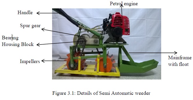
The device is assembled a petrol engine on the mainframe which is modified to accommodate the engine and Bearing Housing Block. Bearing housing block assembled with driven shafts, sprockets and spur gear train etc. Proper safety precautions are identified and provided to take care of chain, sprockets, gears etc. Two similar rollers are mounted under the main frame.
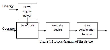
Rollers are fabricated with blades. Petrol engine starts by pulling the thread and knob arrangement. There is a throttle lever, electrical cut-off switch and petrol tank which are mounted on the handle to operate easily. The device can keep in the right position on the field. The engine starts by pulling the thread by keeping the throttle in zero position. Operator can operate the throttle by which the front roller rotates anticlockwise and the rear roller rotates in the opposite direction. While pushing action, weeds are uprooted by the front roller and the soil gets loosen and rear roller does the burying action simultaneously.
Product development methodology (1) is used to develop a new product. It is very important to know the needs of the customers. For this purpose numbers of customers (farmers) are selected from different locations as shown in the customer selection matrix.
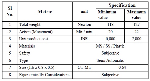
For my interview total of 16 customers are selected so that needs can be gathered in a more effective way and a better product can be generated. The customers include owners as well as operators, shop people and teaching experts. Based on their opinion metrics are developed and target values are set as shown in the table 2.2
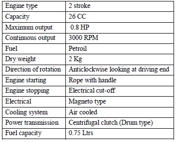
Table 3.1: Petrol engine specification
Roller size: Dia 120 x 125 mm long and Fins: Width 25 x 105 mm long Impellers are designed in such a way that the impeller blades should have sufficient strength in order to poke the field which is in semi solid condition and it should be sharp enough to uproot the weeds.
Material selected is Carbon steel (CS) and its Tensile strength = 250 Mpa
Pressure on semi-solid condition of the field is considered as 4,000 kg/mtr.sq. (Pressure on solid is 15,000 kg/mtr.sq) Scooping area by individual impeller = 2.5 cm. x 10.5 cm = 26.25cm.sq. i.e. 0.002625 mtr.sq. Force = Pressure x Area Hence, the force on the impeller will be 4,000 x 0.002625 = 10.5 Kgs = 103 N. A consideration will show that there will be 3 impeller blades in action at any instant and 2 nos. will be partially loaded while the center one is fully loaded. Hence, the total load (Force) on the impeller will be 10.5 x 2 = 21 Kgs = 206 N.
• Due to the selection criteria depending on the dia. of the roller, the preliminary selection of a simplex chain sprocket of 14 teeth with ½” pitch is selected to mount over the first impeller.
• The similar roller is placed at the rear as front driving roller, but the rotation of the impeller in reverse direction in order to create the easy movement while burying action of weeds
. • Simplex ½” chain is considered for adequate length
• Since the concept of these rollers has to rotate in opposite direction, a gear transmission of spur gear train is selected.
The prototype was taken to University of Agricultural Science, GKVK, Bengaluru for testing purpose and to validate its performance on the wet field. This project was developed based on the continuous interaction with GKVK staff Shri.H.Eshwarappa, Professor (Retd) and his team for developments based on their valuable support, suggestions with encouragement.
Wet land condition was prepared to a distance of 10 Meters on a straight path. Semi automatic weeding device was placed at the one end and the engine was switched ON by pulling the thread. Weeding operation test conducted by pushing the device in one direction and time taken to reach 10 Meters was 28 seconds (appr).
This product was designed and developed on the existing manual weeder by implementing Petrol engine, sprockets, shaft, chain and gears with few modifications on the mainframe. Overall weight of the device is about 14 Kgs which can be easily handled by a person in the field. Handle is made such a way that, to adjust person’s height. Handle grip is provided to hold the device in appropriate position and easy to operate. Throttling lever is fixed at the right side near to the handle grip so that, operator can actuate the lever very comfortably.
Electrical cut-off switch is fixed at the left side of the handle to stop the engine. The device is designed for ergonomically consideration for its operation only to push in the forward direction such a way that the front roller rotates in the anti-clockwise and the rear roller will rotate in the opposite direction. Front roller uproots weeds and loosens the soil and rear roller buries those uprooted weeds simultaneously. The device moves forward direction due to the engine shaft rotation and by manual pushing action.
• The total outcome is named as “Semi Automatic weeder”.
• It is faster than the existing manual Cono-weeder.
• Human fatigue is comparatively less and thereby increases in productivity.
• The device can assemble and dismantle easily on a table.
• Spare parts can replace with the use of simple tools.
• High efficiency of uprooting & burying weeds.
• Easy to operate with minimum skill level.
• Product cost is reasonably economical for even medium size field farmers.
• Handle can be made adjustable to suit the operator’s height.
1. Karl T. Ulrich., Steven D Eppinger, Product Design and Development, Tata McGraw-Hill, New Delhi, Third Edition in 2003
2. IS 800 and CMTI data hand book.
3. Renold catalogue: ½” simplex roller chain, ISU type-A, Chain no: 110046. ISO chain no OBB-1
