


Published on Sep 03, 2023
Due to the increasing energy demand of the human population, to keep the sustainable development, there is a major need for the utilization of alternative energy sources. Hence a promising need to identify an alternative to petroleum products, that is indigenous and renewable energy source has become all that important. Renewable energy sources, among them, gases used could be an effective alternative to fulfil remarkable part of this energy demand as a possible solution of decentralized power generation.
At the same time, in order to meet the more stringent emission regulation that has been implemented all around the world, there are still technical difficulties to be resolved to simultaneously reduce the emissions from the engines.
Producer Gas, derived from biomass gasification, as an important renewable and economical energy source for both heat and electricity generation, is being recognized for its true potential and use for the benefit of rural population as well as urban industry. Such a development needs basic research on combustion and gasification processes. One of the applications of biomass based producer gas is, using it as a fuel in reciprocating internal combustion (IC) engines which in turn can be used as power source.
The various means of incorporating the producer gas in the I. C. Engine needs extensive research. For this purpose, one needs to develop/adopt a suitable I.C. Engine design and its operating parameters. Carburetor is one of the important components in such category and it is identified that additional research work is to be carried out in establishing a design procedure. In this paper, a review has been carried out about the different designs as well as simulation work available for Producer Gas Carburetor.
Biomass as energy is gaining importance as a renewable source to strengthen the country‘s agriculture as a prime player in Indian economy. The use of biomass for thermal energy is ancient but the biomass as a renewable energy source implying clean combustion process is more recent. In the last three decades the Ministry of New and Renewable Energy (MNRE) of Govt. of India, has encouraged R&D in developing gasification systems in India. In most of these developments, CGPL, IISc (G. S. Sheshagiri, et al, 2009) is at the forefront bringing its knowledge on advanced combustion processes to handling solid fuels. As the maps are made available through Web atlas the changes are accessible to remote clients as soon as the server is updated. The web site also provides the biomass data in tabular form for easy emanation of data for use. Country‘s Agro-biomass power potential is found to be above 15000 MWe. This is exclusive of Biomass from Bamboo, Non-edible Oil cakes, urban wastes, Wood, Major part of Agro-forestry and Waste land.
Mixing devices for gases used in gas engines generally referred to as carburetor, for mixing air and gaseous fuels are commonly attached to the intake manifold of an internal combustion engine. In gas carburetor the mixing of air and gaseous fuels needs to be in a proper ratio for particular demand of the engine. In the current state of technological advances, it is recognized that Biomass is one of the viable and sustainable renewable resources and new technologies emerging out of biomass based gasification systems find a significant role in bridging the energy crisis. The advanced biomass gasification systems are known to generate producer gas as the combustible fuel that is clean enough to be used in gas engines. However in order to use the standard gas engines some of its components need modifications before they are used to handle this gaseous fuel.
With increasing demand for high fuel efficiency and low emission, the need to supply the engine cylinders with a well-defined stoichiometry mixture under all circumstances has become more essential for better engine performance. Carburetors are in general defined as devices where a flow induced pressure drop forces a fuel flow into the air stream. An ideal carburetor would provide a mixture of appropriate air-fuel (A/F) ratio to the engine over its entire range of operation from no load to full load conditions. To ensure proper industrial dissemination these special Carburetors should be reproducible and should have standardized operating procedures. Design of a gas carburetor for application with gases of low energy content here producer gas is considered for its geometrical and performance optimization. The device is meant for generation of an optimal air-fuel mixture to meet varying load conditions of the engine and at varying supply pressure of the fuel.
Research work on an experimental analysis on Producer Gas as a reciprocating engine fuel was presented at IISc Bangalore (G. Sridhar, et al, 2001) in which Producer Gas was used in high Compression Ratio engine as discussed below.
The essential features in the gas carburetor are
• Ability to maintain req. air-to-fuel ratio (1.2 to 1.5:1) with load or throttle variation
• Smooth operation with minimal pressure loss
• Shut off the fuel in case of engine tripping or shut-down
• On-line provision for air/fuel tuning during testing
The carburetor is simple in design and does not have moving components. It has a separate port for air and fuel, where the individual ports could be modified or tuned to achieve the required air-to-fuel ratio. The carburetor is designed to operate in conjunction with the zero-pressure regulator. The combination of pressure regulator and gas carburetor was located between the gasifier and the engine intake system as shown in Figure 1.
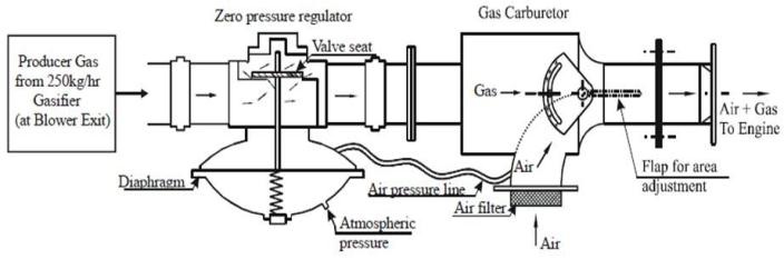
The zero pressure regulator ensures a gas pressure (downstream of the pressure regulator) identical to that of air pressure and this is achieved by connecting the air pressure line (downstream of air filter) to the upper chamber of the regulator. This arrangement ensures the regulator to maintain the gas pressure close to that of air pressure (~a few mm below atmospheric pressure) and thereby the set air/fuel ratio irrespective of the total mixture flow rate.
Flow tests performed with zero-pressure regulator and the gas carburetor showed reasonable functioning in terms of air-to-fuel ratio control against total or mixture flow rate variations as shown in Figure 2. Flow test was conducted using a blower to simulate the engine suction. The air and fuel flow rates were individually measured over a range of engine‘s operating conditions.
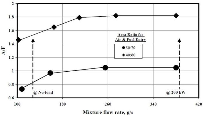
The two cases shown in the above figure correspond to area ratios for the air and fuel entry. These cases are possibly the extreme limits and the required operation point for the engine operation could lie in between them. The A/F ratio was reasonably constant beyond a specified mixture flow rate, with relatively rich mixture at low mixture flow rates. This characteristic is desirable from the viewpoint of engine operation – rich mixture for engine start-up and no-load operations, relatively leaner mixture during part load operation. However, for peak load operation – stoichiometry or rich mixture is desired calling for the adjustment of the carburetor flap. Considering gas engine operation at the field level, the carburetor is designed in such a manner that in the event of load throw-off the flap of the carburetor could move to full air flow (by motorizing) condition thus ensuring safety of the engine.
The main disadvantage of above design of carburetor being that for different A-F ratio requirements the adjustment of the carburetor flap has to be done manually, which is not possible in on-duty operation. It has to occur automatically. The problem is mainly noticed during sudden load change and load throw off conditions because of hysterisis and sluggish response of the carburettor. When the engine is running at high load, the mixture flow rates will be very high in order to meet the power demand.
Under this condition of high flow rate, if there is sudden and drastic fall of load on the engine or the load is completely thrown off, the speed of the engine starts to increase and to prevent this the governor comes into play and reduce the throttle valve opening possibly with some overcorrection especially during load through offs. This sudden closure of the throttle valve leads to pressure build up upstream of the throttle valve. When Engine is used for grid application the hysterisis and sluggishness of the zero pressure regulators generally leads to the richening of the mixture which cause backfiring problems.
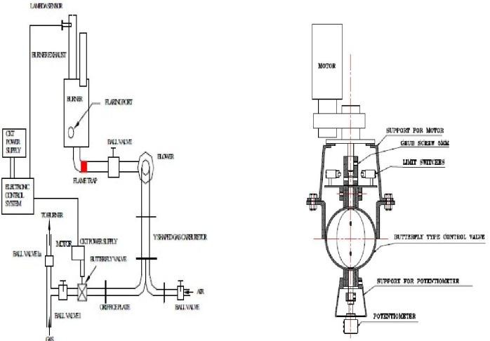
It consists of the T-shaped gas supply line containing different valves for flow control of the gas and air as shown in fig. 3 The stoichiometric air to fuel requirement ratio varies between 10 to 6 (on volume basis) for fuel such as natural gas and biogas/landfill gas based on methane content in the gas. However, stoichiometric air to fuel ratio for producer gas is about 1.2 to 1.4 (on volume basis) based on constituents of gas. So it is necessary to have the carburetor which will maintain required air to fuel ratio with load variation, smooth operation with minimal pressure loss etc.
Basically a ball valve is used for gas flow rate controls. After the ball valve, a butterfly valve is included in the gas line, which acts to establish fine control in the gas flow rate as shown in fig.3. Butterfly valve is actuated by the geared motor to control the air fuel ratio. Another arm of the setup of carburettor is connected to the air line, which also has a ball valve and orifice plate. Measurement of air and gas flow rates gives an indication of the air-fuel ratio. One of the exhaust pipe has a small hole in which the Lambda sensor is screwed. Another hole is also provided to draw small quantity of exhaust gas for analysis. The Lambda sensor is in turn connected to the electronic control system. The electronic control system triggers the geared motor based on the instantaneous lambda value. The geared motor is connected to the control valve that controls the gas flow rate to the carburettor.
The extensive experimentation with the engine simulating conditions the design of the control and actuation parts with the use of lambda sensor is found to be working suitably. So with the use of feedback control system as shown in fig.4, the lambda sensor based carburetor can provide stoichiometric air fuel ratio and will help in reducing backfiring problem faced during frequent load changes and throw off conditions. Time lag is the inbuilt phenomenon with feedback control systems
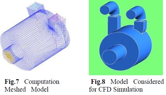
A 3-Dimensional RANS code having unwinding implicit scheme and k–ε approach for turbulence is used for obtaining numerical solution. The Equations are solved for steady incompressible flow. The boundary conditions and initial conditions used include (a) no slip and adiabatic walls; (b) At inlet and outlet ports, pressure and mass flow rate respectively.
A producer Gas Carburetor with zero pressure regulator was designed which ensures the regulator to maintain the gas pressure close to that of air pressure and thereby the set air/fuel ratio irrespective of the total mixture flow rate. The main disadvantage of above design of carburetor being that for different A-F ratio requirements the adjustment of the carburetor flap has to be done manually, which is not possible in on-duty operation. It has to occur automatically. The problem is mainly noticed during sudden load change and load throw off conditions because of hysterisis and sluggish response of the carburetor.
In the extensive experimentation with the engine simulating conditions (Sheshagiri G.S., et al.), the design of the control and actuation parts with the use of lambda sensor is found to be working suitably. In this with the use of feedback control system, the lambda sensor based carburetor can provide stoichiometric air fuel ratio and will help in reducing backfiring problem faced during frequent load changes and throw off conditions.
The mixing chamber model (T. R. Anil,et al.) designed with CFD modeling have been comprehensively analyzed for its mixing performance and response which has shown consistency in the experimental data and the modeling and has provided a good insight into the flow details and optimization in the geometrical design to get a good mixing efficiency.
With this literature review, extensive research work can be carried out with the present Producer Gas Carburetor and further much more development and modifications can be done for the commercial utilization of Producer Gas as a major fuel for I.C. Engines and thereby much of the load on the present conventional fuels i.e. Petrol and Diesel can be reduced with such scope.
G S. Sheshagiri, N.K.S. Rajan, S. Dasappa, P.J. Paul,(2009) Agro residue mapping for India, European Biomass Conference in Hamburg, Germany.
G.Sridhar, P.J. Paul, H.S. Mukunda, (2001) ―Biomass derived producer gas as a reciprocating engine fuel—an experimental analysis‖, Biomass and Bioenergy 21(1) pp.61–72.
S. B.Dirbude, Sheshagiri,G.S., Dr.N.K.S.Rajan,(2005) ―Experim- ental Analysis of Feedback Control System for Lambda Sensor based Producer Gas Engine Carburettor‖.
T.R.Anil, S.D.Ravi, M.Shashikanth, P.G.Tewari, N.K.S.Rajan, (2006) ―CFD Analysis of a Mixture Flow in a Producer Gas Carburetor‖, International Conference on Computational Fluid Dynamics, Acoustics, Heat Transfer and Electromagnetics CFEMATCON-06,Andhra University,Visakhapatnam INDIA.
R. B. Yarasu, Vaibhav Nadkarni, P. J. Paul, (2005), ―Laminar and turbulent burning velocities of premixed hydrocarbon-air flames in closed cubical vessel‖, Proc. of 19th NCICEC, Chidambaram, India, 19:335-341.
