

Published on Apr 07, 2026
This project revels the manufacturing of Electro Magnetic Clutch. In place of Engine, shaft is directly attached to variance (variable motor) and clutch disc as well as pressure plate is used, in between them friction material called "Asbestos" used to grip between the pressure plate and clutch plate. This project shows, experimental analysis of Electro magnetic clutch, and at last at which speed clutch engage as well as disengage is measured and when clutch disengage, at that time speed of flywheel is also measured
• Function of clutch is to engage or disengage the engine from the transmission system. Hence it is inserted between the flywheel as well as gear box. It is consists of main important parts like clutch plate, pressure plate, friction disc, operating lever etc.
In clutch engage as well as disengage are very important, because due to which clutch is used. But when clutch is applied at that time, some clearance is there in the clutch pedal called clutch pedal play and due to which, proper disengage of clutch is not achieve and clutch will slip or dragged.
• There is a need to use some system incorporated in clutch system, to prevent above situation. Hence, if we shift gear and at that time clutch will disengage hence the it is very simple for driver and force require to engage as well as disengage the clutch is also neglected, hence a new type of clutch used in automobile vehicles called "Renault Car" called electromagnetic clutch.
• In this clutch system, when gear shift lever is applied at that time, due to MMF clutch will disengage and when release lever, clutch will engage.
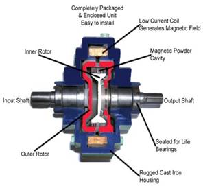
The clutch has four main parts: field , rotor , armature , and hub (output) (Figure-22). When voltage is applied the stationary magnetic field generates the lines of flux that pass into the rotor. (The rotor is normally connected to the part that is always moving in the machine.) The flux (magnetic attraction) pulls the armature in contact with the rotor (the armature is connected to the component that requires the acceleration), as the armature and the output start to accelerate. Slipping between the rotor face and the armature face continues until the input and output speed is the same (100% lockup). The actual time for this is quite short, between 1/200th of a second and 1 second.
Disengagement is very simple. Once the field starts to degrade, flux falls rapidly and the armature separates. One or more springs hold the armature away from the rotor at a predetermined air gap.
