
Published on Apr 07, 2026
In the present paper the analysis of the leg movements of mechanical spider robot has been done. A mechanical spider is an eight leg robot which works on klann’s mechanism and can be used at bumpy roads, hilly area or any type of surfaces. Engineering specifications and requirements for the design of an artificial mechanism are the main objective of this paper.As fantastic as this idea may seem, recent developments in electroactive polymers (EAP) may one day make such bionics possible.
As this technology continues to evolve, novel mechanisms that are biologically inspired are expected to emerge.In recognition of the need for cooperation in this multidisciplinary field, there is a series of international forums that are leading to a growing number of research and development projects and to great advances in the field. In this paper, the field of EAP as artificial muscles will be reviewed covering the state of the art, the challenges and the vision for the progress in future years.
Introduction to Klann’s mechanism is an expansion of Burmester theory that converts rotary motion of the crank to linear movement of the foot for one-half rotation of the crank and raises the foot for the second half, returning it to the starting point. Two of these linkages, 180 degrees out of phase, will function as a wheel replacement. The Klann’s linkage is a planar mechanism designed to simulate the gait of legged animal and function as a wheel replacement. The linkage consists of the frame, a crank, two grounded rockers, and two couplers all connected by pivot joints.
The proportions of each of the links in the mechanism are defined to optimize the linearity of the foot for one-half of the rotation of the crank. The remaining rotation of the crank allows the foot to be raised to a predetermined height before returning to the starting position and repeating the cycle. Two of these linkages coupled together at the crank and one-half cycle out of phase with each other will allow the frame of a vehicle to travel parallel to the ground.
A single leg is a six-bar linkage that consists of the frame, crank, connecting arm, lower rocker, leg and an upper rocker. The ground points for the upper and lower rocker in this configuration are vertically in line to allow a coupled pair of legs to articulate like the front wheels of a typical car for steering. The Klann linkage provides many of the benefits of more advanced walking vehicles without some of their limitations. It can step over curbs, climb stairs, or travel into areas that are currently not accessible with wheels but do not require microprocessor control or multitudes of actuator mechanisms. It fits into the technological space between these walking devices and axle-driven wheels.
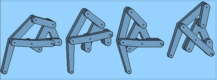
These figures show a single linkage in the fully extended, mid-stride, retracted, and lifted positions of the walking cycle. These four figures show the crank (rightmost link in the first figure on the left with the extended pin) in the 0, 90, 180, and 270 degree positions.It has been a hobby for a number of years to develop a bicycle without wheels that could walk. It would move on legs and resemble a large insect. A linkage was developed that satisfied the design criteria and several small-scale prototypes were built that demonstrated the concept. Applications for the linkage go beyond human-powered machines. The links are connected by pivot joints and convert the rotating motion of the crank into the movement of a foot similar to that of an animal walking.
The task of finding innovative concepts of spider-inspired attaching mechanisms, as well as suitable locomotion strategies for engineering devices, will be tackled in this research.The spiders’ ability of walking and climbing on different surfaces and in different conditions of slope will be very useful if mimicked with the purpose to create robotic prototypes that can explore extra-terrestrial surfaces.The remarkable progress in manufacturing automation and robotics in the second half of the 20th century allowed replacement of humans in dangerous, inaccessible working environments.
With the progresses in nanotechnology and micro robotics appeared the possibility of creating autonomous miniature structures used for a wide range of tasks which could not be realized prior, like the use of robots in securing land-mined areas, inspection of large mechanical structures that present hazard (e.g. electric poles),exploration of narrow and inaccessible environments like underwater structures, industrial pipes or outer-space exploration.Exploration in these non-structured environments required robots along with low mass, high motion capabilities, climbing abilities and embedded decision elements .The autonomous working capacity, without any linkage to a mother-structure, and a very low energy consumption, are two of the most important requirements to satisfy in order to develop such a devices.
Different types of locomotion have been attempted in order to allow all-surface locomotion, but some of the methods, like air-suction and electromagnets, presented the disadvantage of very limited autonomy because of the power supplies needed in order to work, along with the limitations introduced by the surfaces that those mechanical structures will be able to moveupon and by the lacking of grip. So, the attention turned to biological creatures that were able to climb fast and run over various types of surfaces in unstructured environments and in different weather conditions. Replicating these creatures, like spiders, lizards (especially gecko lizards) or insects was no easy task because the manufacturing procedures were not available.
Moreover the locomotion techniques used were not fully understood and advanced researches needed undergone using modern measuring and observation equipment’s. The techniques used by the insects, spiders and reptiles include the use of claws to grasp on the asperities of the surface, the use of wet adhesives, in the case of some flying insects, the use of dry adhesives in the case of the gecko lizard, or the mixed use of claws and dry adhesives, like in the case of the spiders. The first one method, the claws, is used by the animal for interlocking with the asperities of the surface.
The second one, the adhesion forces, appears between the environment and the hairs present on the limbs of the insects. For the further development of wall climbing robots the spider locomotion modalities are of most interest, given the actual manufacturing and research possibilities, so the locomotion of these creatures will be subject of study. Against gravity by frictionless contacts mounted under the mechanism.
In general, a spider-like robot must have at least three limbs in order to move quassistatically in planar tunnel environments. At every instant the spider braces against the tunnel walls in static equilibrium using two or three limbs. During a 2-limb posture the spider moves its free limb to the next foothold position. During a 3-limb posture the spider changes its internal geometry in preparation for the next limb lifting.
The invention provides a walking device which stimulates a gait of a legged animal. The device includes a frame with spaced axial mounts, a leg, axially connected upper and lower rocker arms which limit reciprocating leg motion. The leg is driven by a connecting arm powered by a rotating crank. The position and configuration of the axial connecting sites establish a prescribed orbital path that the foot undertakes with each revolution of the crank. Both rocker arms and the crank are axially mounted to the frame.
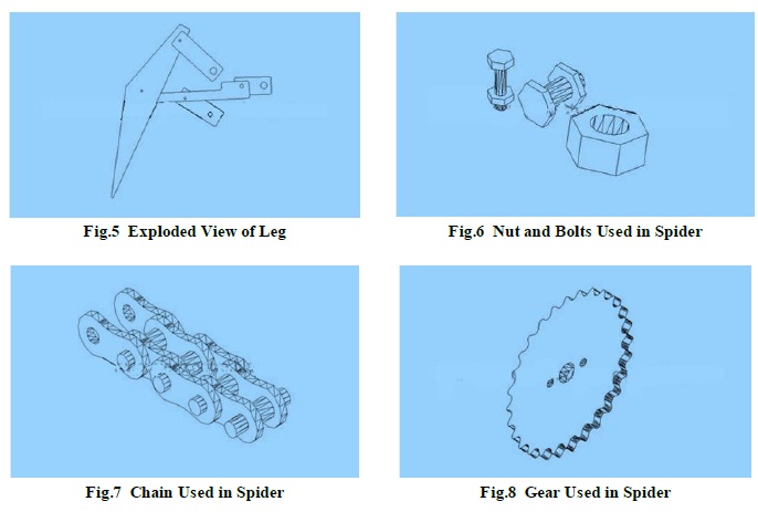
The leg has a hip joint axially connected to the upper rocker arm for limiting hip motion, a foot and a knee joint axially connected to the connecting arm. The connecting arm has three axial connecting sites, one for connecting to the knee, another to the crank, and a third connecting site defined as a centrally disposed elbow joint connecting site which connects onto the lower rocker arm and limits knee joint motion.
Under power, crank rotation is transferred to the connecting arm causing the leg to move in an accurate reciprocating movement of a restricted actual pathway which stimulates the gait of the legged animal. The walking device may be manually powered or motorized by applying motorized power to the crank axles.
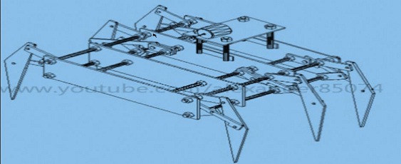
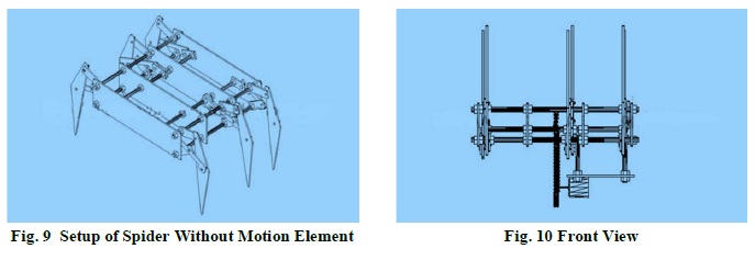
ENERGY EFFICIENCY-In our design we want to minimize the amount of energy used per locomotive cycle. We will accomplish this by designing a linkage which minimizes torque on the crank and sequencing a gait in which the upward movement of one leg is cancelled out by the downward movement of another leg; this necessitates that the walker have 6th legs. Additionally, these legs must be attached to a central crank axis so that they can be coupled. The legs will all be directly coupled to the same crank axis. The linkage will also allow the main body of the vehicle to remain at a constant height throughout locomotion, which will minimize energy losses due to changing potential energy.
ABILITY TO AVOID OBSTACLES BY STEPPING OVER THEM-As we explained in the previous section, the main reason for choosing a walking mechanism over a wheel is that it has the ability to avoid obstacles. The linkage must be designed in order to maximize this advantage.
STATICALLY STABLE DURING ENTIRE LOCOMOTIVE CYCLE-It is our aim to make a vehicle that is not prone to falling over. If the vehicle should come to a stop at any point in the locomotive cycle, the vertical projection of its centre of mass must always be inside its base of support.
DURABLE JOINTS/HINGES/MOVING PARTS WHICH WILL NOT BECOME BLOCKED BY DEBRIS OVER TIME-Since this walker will be moving across uneven terrain, it will most likely encounter obstacles that it cannot avoid. The linkage must be able to handle the stresses of irregularities in the terrain. The vehicle will be walking outdoors so the linkage should not include cam grooves or other parts that may become blocked by debris.
INEXPENSIVE MATERIALS- We are working with a limited budget, so I would like to design a mechanism that can be built with inexpensive materials. This means limiting the use of parts such as bearings, hinges, springs… etc.
NO CONTROL MECHANISM NECESSARY-This mechanism will not be operated by a computer or a person via a hydraulic system. Instead, it is my intention to build a walker with a passive, periodic gait for the purpose of simplicity.
The spider bike linkage is a basic concept similar to a wheel made out of stone. Wheels today are still round but improvements in materials, construction, drive train, braking, and suspension have increased their usefulness and efficiency. They are used on a wide spectrum of things from small toys to huge pieces of mining equipment. This linkage will evolve in much the same way. Different uses will have different requirements that will drive modifications and advancements. Some of the obvious ones are listed here.
FOOT DESIGN-There will be a general-purpose foot designed for a variety of terrain types that could handle sand, rocks, or pavement. Specialized feet will be developed to target specific conditions such as sidewalks, curbs, or stairs and for amphibious vehicles that are expected to travel in wet marshy areas or extreme rock climbing vehicles requiring more traction.
SUSPENSION-There are several areas that could be utilized for adding suspension. The foot, leg, shock absorbing links, or attachment points to the frame are several possibilities.
COLLAPSIBLE-The frame and legs for small and mid-sized applications would benefit froma collapsible configuration to increase options for storage and delivery to target. A parallel linkage between the frame and each pair of legs similar to ATV suspensions could be exaggerated to allow the legs to fold up against the body when fully lifted.
AMPHIBIOUS-The legs can function as oars enabling the vehicle to paddle in the water. This could be a passive design such as fixed canards, hinged flaps, or openings designed into the legs that would minimize the drag during the forward stroke on the portions of the leg that are not lifted above the waterline and take advantage of the motion of the leg on the return stroke to propel the vehicle forward. A midpoint on the foldable suspension mentioned above would position the legs to optimize the movement of the legs when rowing. A walking machine with the ability to climb over obstacles and swim across rivers would eliminate many of the restrictions of conventional vehicles.
LEADING EDGE SPURS-Teeth on the front edge of the legs allow the spider to step onto obstacles taller than its step height, the highest point of the foot during a cycle. The downward motion of the leading leg will lift the body of the device if the spurs remain engaged until the paired leg contacts the obstacle and continues to increase the overall centre of gravity.
TRAILING UNDERCARRIAGE SPURS-A single large protrusion on the trailing edge of each leg, if appropriately designed, would enable the vehicle to crawl over obstacles that would otherwise limit it based on ground clearance. The translation and rotation of the leg during the propelling portion of the cycle can be transferred with this modification.
SPRING ASSIST-The use of springs to counter balance the momentum of the legs as they move throughout the cycle would have benefits. The ideal configuration would use springs with the appropriate stiffness to create a system at resonance for a specific target speed.
BUCKLING LEG-Toys would benefit from a leg that would unsnap or provide spring-loaded relief when stepped on or dropped. Larger vehicles could be designed with shear pins or breaking points that would minimize structural damage during collisions, jumps and falls.
HYBRID LEGS-Additional degrees of freedom could be added to the device by controlling the length of various links with actuators. The added complexity could have benefits. It would allow for precision placement of the foot, increased step height, and still allow high speed traveling when the standard length is locked in.
SPEED-LEVELING DRIVE TRAIN-The variation in the speed of the foot for a constant rotational speed of the crank is not desirable. A variable crank rotation that could compensate for these differences as well as the mechanical advantage needed when stepping onto obstacles would minimize the stresses on the drive trains of larger vehicles.
Electronic Braille readers, agile planetary rovers and solar-powered drones that mimic birds in flight are just some of the envisioned applications that could get a practical workout as developers flex the capabilities of an emerging concept called artificial muscle. Generally, imitating nature offers many advantages, since nature came up with numerous inventions that work and last. But sometimes, it is better to be inspired by nature rather than make an exact copy. Examples of copying include the use of honeycomb, Velcro, fins for diving and many others.
However, copying the wings of birds as a means of flying did not work, and we as humans had to learn the principles of aerodynamics in order to be able to fly. Once those principles were proved out in rudimentary aircraft, subsequent engineering improvements produced machines that far exceeded the capabilities of birds in terms of speed, distance and load capacity. Making artificial muscles at this point falls into the latter category of being inspired by nature rather than imitating nature. This work studied the spider system in a bio-mimetic perspective.
In particular the mechanisms that allow the spider to climb and overcome most of the existing surfaces and obstacles are evaluated. The attention focused on the Spiders’ legs in order to search and define both how the spider can climb and walk on different surfaces and how a spider-inspired robotic system can be built in order to assure such abilities. Once defined the conditions to exploit and activate the attaching systems, the evaluation of the kinematics of the real spider has been done. Then, a new spider-model for a robotic prototype has been developed.
The overall kinematics of the system has been solved starting from the analysis of the simplified leg model. Then, a locomotion strategy inspired by the real pattern of the spider has been studied and evaluated .The spider-model, the overall kinematics and the locomotion strategy have been implemented in a simulator that confirmed the validity of our choices.
[1]. J.N. Hung, taxonomic study of Myrmarachne, (Araneae: Salticidae) from Taiwan.
[2]. J. C. Spagna, D.L. Goldman, P-C. Lin, D.E. Koditschek and R. J. Full, Distributed Mechanical Feedback in Anthropods and Robots Simplifies Control of Rapid Running on Challenging Terrain, Bionspir, Biomim, Vol. 2, No.1, 2007
[3]. A.B. Keswl, A. Martin and T, Seidl,, Adhesion Measurements on the Attachment Devices of the Jumping Spider Evarcha Arcuate, J. Exp. Biol. 206 (203), pp. 2733-2738
[4]. R. Ruibal. And V. Ernst, The Structure of the Digital Setae of Lizards, J. Morph, 117, 271-294, 1965.
