


Published on Mar 01, 2025
The present paper deals with design, construction and working of Accelerator and Brake operated by one pedal, which may be a technique for reducing road accidents. The main objective of this innovation is to eliminate the operator’s risk of pressing the wrong pedal at the time of emergency as well as reduction in the driver’s reaction time to switch from accelerator to brakes or vice versa. This new mechanism is designed in such a way that it can be used in any type of automotive vehicle. The mechanism used for combined brake and accelerator is simple and can be adopted conveniently.
At the present time automobiles are equipped with independent pedal controls for operating the accelerator and brake, these pedals being operated by right foot, and since the two functions are opposed and incompatible it is necessary to leave one pedal free in order to operate the other. It can therefore be supposed that some drivers have difficulty in removing their foot from the accelerator pedal and transferring it to the brake pedal quickly in emergency situations. To solve this problem, a new brake pedal and accelerator system is designed. The detailed design of combined pedal mechanism is modelled using CATIA V5 R20. Then a prototype has been prepared which confirms the required mechanism and finally tested for its working. Therefore, it gives an optimized design for new combined pedal mechanism. Hopefully this project will help everyone to understand how implemented mechanism works more efficiently, which can help to reduce the accident that may happen in each day.
Nowadays the increment in the death rate of India is 20% because of the accidents on the highways hence this innovation can help us to reduce the death rate by 7% to 10% since this can be used in the any 4 wheeler. The innovation relates to the improvements in the mechanical movements and has a particular reference to a Combined foot brake pedal and accelerator pedal movement. It essentially consists of a joint pedal for operating the brake and accelerator, arranged in such a form that its action to affect one or the other function is carried out without the possibility of error, and without one function interfering with the other. As conventional pedals are equipped with separate brake and accelerator.
The clutch is to the left, the accelerator to the right and the brake in the middle. The right foot should be used for pressing the accelerator and brake. The arrangement guarantees, that the throttle is released as the driver brakes. However, it also means that the foot is almost always placed at a distance from brake, that is, on the accelerator, thus movement time adds to brake reaction time. The foot may be inaccurately placed on the brake resulting in bad braking performance and it may even miss the brake and hit the accelerator. It is being observed that it takes longer to brake in an emergency with separate pedals. It takes at least 0.2 seconds to move your foot from one pedal to other and hence, at 80 kilometres per hour this adds five meters to vehicle’s stopping distance. Moreover, due to sight misjudgement it is easy to hit the wrong pedal which leads to accelerator being clipped, causing a crash.
In order to eliminate such kind of problems, A COMBINED PEDAL MECHANISM is designed to function as both BRAKE and ACCELERATOR, which can be adopted by driver quickly and effortlessly. This new mechanism enables the driver to control acceleration and braking using one feet, which will lead to reduction in stopping distance, misjudgement and ultimately decrease in number of road accidents that may happen each day.
The design of new mechanism aims, to provide a pedal that applies the brakes instantaneously and also permits the operation of accelerator with the same foot. In other words, the vehicle must not accelerate at the time of braking and at the time of acceleration vehicle must not decelerate or stops.
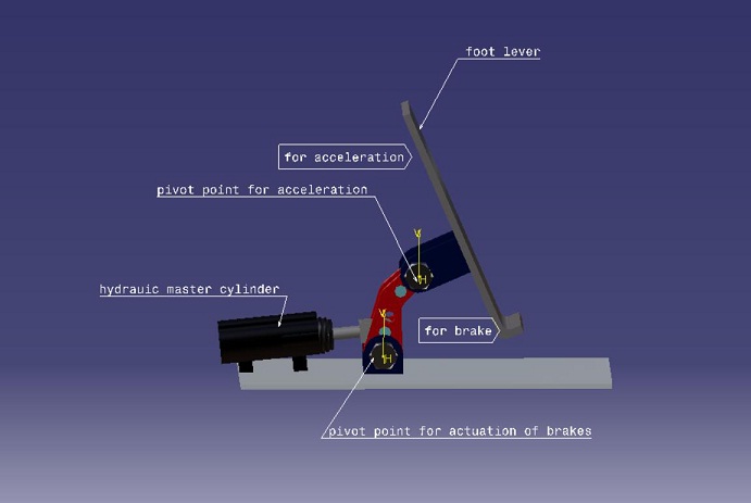
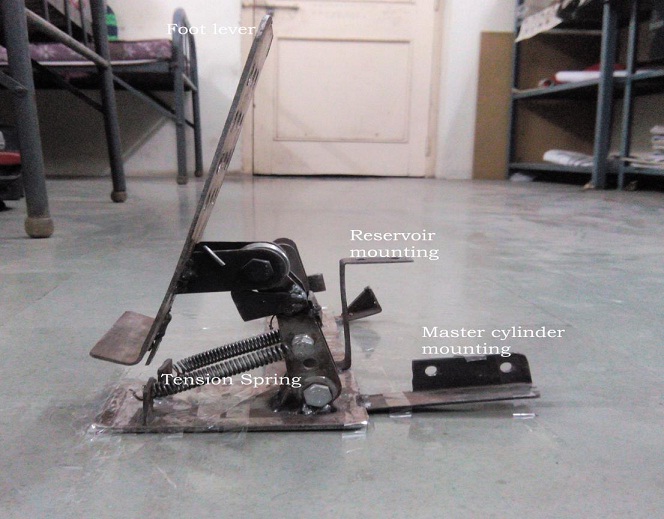
The design of mechanism was prepared on 3D modelling software CATIA V5 R20 shown in figure 1, after that, a working model is prepared using mild steel (AISI 1018) as material. It consists of a base plate say, 3mm thickness on which the whole mechanism is to be constructed. The lever is mounted over the base plate which is free to rotate in any direction, its forward movement is controlled by stroke of master cylinder and backward movement is controlled by two helical tension springs arranged in parallel, which helps the lever to come back in original position.
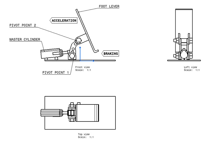
In addition, another purpose of spring is to restrict the movement of lever during throttling. At the top of the lever 2nd pivot is provided on which the foot lever is clamped which is also free to rotate in any direction. Figure 2 represents drawing of the combined pedal mechanism, which illustrates all three views for better understanding. It shows foot lever is directly attached to pivot point 2 using a M8 half threaded bolt, which gives angular moment to foot lever. Similarly, pivot point 1 is created on base plate, which enables linear movement of push rod into the master cylinder.
The pedals mounted at the centre of a vertically displaceable pivot. The ends of the pedal serves as accelerator and brake. To accelerate driver, pivot the pedal while to Brake driver, push the entire pedal mechanism forwards. So, Accelerating is a feet movement and, while braking comes from extending whole leg. A driver can switch from acceleration to braking instantly, just by pressing the combined pedal forwards. A few potential disadvantages with the combined pedal may be noted.
One significant problem is the risk for confusion when the person that is familiar with separate pedals for the brake and accelerator must relearn these actions when required to use the combined pedal. The most obvious danger is that drivers will move their foot away from the pedal, particularly in emergency situations. A corresponding problem can arise when the driver, who is accustomed to the combined pedal, returns to the system of separate pedals. In this latter case, the driver stretches his out his or her leg during braking and hence inadvertently presses the accelerator instead of the brake pedal.
A second possible hazard concerns an ergonomic problem. If the driver has difficulty in relaxing because of concern for unintentional braking, physical tension and strain likely to occur. The third imperilment is that the shortened reaction time in braking in combination with the increase in flexibility can bring about what is known as the compensation phenomenon. Concern has been most intense for problems associated with driver confusion. While an individual probably face little difficulty to relearn, in that case it would be difficult to recommend combined pedal, even though it is likely a better solution than traditional pedals.
At the introduction of the combined pedal system, the vehicle population would consist of vehicles with divergent pedal systems for a considerable number of years. This inevitably would entail a large number of hazardous traffic situations because drivers are continuously required to switch between pedal systems. Consequently, an initial controlled evaluation of combined brake-accelerator pedal should focus on highlighting the eventual problems that may occur during the transition period between the combined pedal and the conventional pedals. The purpose of the present study, therefore, was to examine the potential transition problems as outlined earlier.
In order to accelerate, the foot lever rotates about pivot point 2(upper pivot point), Figure 4 shows the upper half of foot lever moves in downward direction and lower half of pedal moves in upward direction i.e rotation of foot lever would be in anticlockwise direction. However, the support is kept in stationary position, this resistance is achieved by using helical tension spring. The main purpose of spring is to provide Resisting force to the support during throttling. Hence, by using upper half of the foot, driver can accelerate the vehicle without actuation of brakes.
In order to brake, the foot lever and support both moves in linear direction such that, there would be no acceleration of the vehicle. This is achieved by fixing the source (acceleration cable) at the bottom end of the pedal near the heel rest. Therefore, the whole assembly (foot lever, support) rotates about the pivot point 1 and spring comes in stretched position. On releasing the pedal, the spring tends to come in original position due to spring action. Hence, driver can decelerate or stop the vehicle without actuation of throttle.
In this condition foot of driver simply rests on foot lever, it does not cause either of the function. Figure6 shows the positioning of foot, any further movement results in acceleration or braking.
With the above study we can conclude that this new mechanism results in avoiding interference of braking during acceleration and vice versa. Moreover, it is advantageous over conventional pedals. This combined pedal mechanism thus provides a driving control which permits the quick and smooth transition from acceleration to braking, without needing to transfer the foot from one pedal to another. The rapid increase in number of vehicles on roads day by day, demands an exploration of such mechanism to get rid of driver’s effort and reduce road accidents.
[1] Rickard Nilsson, 2002, Evaluation of combined brake-accelerator pedal, Accident Analysis and Prevention, 34, pp. 175-183.
[2] http://www.google.com/patents/US3331479
[3] V.B. Bhandari, “Design of Machine Elements”, Published by Tata McGraw hill Education Private Limited, third edition copyright © 2010.
