


Published on Mar 01, 2025
Pneumatic conveying system is a conventional material handling system like belt conveyor or chain conveyor. The main advantage of pneumatic conveying system is that material is transferred in close loop, thereby preventing the environmental effect on the material and vice versa. In these topic different parameters like air velocity, pressure, particle size and shape, distance to be conveyed, which govern the design of the system, are described. The research work carried out on the pneumatic conveying system in the last decade considering these parameters are also presented.
No standard procedure is available for the design of pneumatic conveying system. As the configuration of the system changes, variable involved also changes, and one has to change the design considerations based on the applications. So there is wide scope for experimentation in the field of pneumatic conveying system.
Pneumatic conveying started in 1866 with the application of a fan and ducts to remove the dust and fine particles from woodworking operations. Since then, the field of pneumatic conveying has greatly expanded to include nearly all fine granular bulk materials in the chemical, cement, agricultural, pharmaceutical and food processing industries. Unfortunately, the art of pneumatic conveying is still very empirical and can lead to many misapplications. Research is still being done by many universities around the world, but the theoretical solutions for “two-phase flow” are often too complex for the practicing engineer. Besides, many of these solutions require experimentally-derived coefficients, which are not readily available.
Venturi educators have no moving parts allowing for maintenance bulk solids. In applications involving fine, abrasive, or irregularl this is an enormous advantage. Replacement of existing rotary airlocks with venturi eductors makes for simpler, more reliable conveying systems. Designing with educators from the beginning ensures the most reliable product feeding availa All rotary airlocks have blowback. If the product conveyed is fine or abrasive, blowback can cause extreme wear problems. Even with free blowback can be a problem, causing bridging and housekeeping problems, or even an explosion hazard. When installed beneath bughouses, screw conveyors, or dust collectors, airlocks can be a major source of fugitive dust emissions, which are eliminated after a retrofit to eductors.
Eductors have none of the shearing, smearing or degradation of product common with rotary airlocks. And, of course, safety is simply not a concern with eductors. One of the most common applications for eductors is their installation under dust collectors, replacing screw conveyors and airlocks with a better solution with no dust or moving parts. One blower can simultaneously drive many eductors.
Pneumatic conveying systems are generally sinuous. A very wide variety of materials can be handled and they are fully enclosed by the System and pipeline. Based on the quantity of air used and pressure of the system. A typical pneumatic conveying system comprises of four basic units, air mover (Blower), feeder (Hopper or Silos), and conveying pipe line loop and filtration unit. Feeder is a device that is intended to feed the material in to the conveying loop uniformly and that to with lowest leakages. Numerous devices have been developed to feed the materials in to the pipelines.
Some of them are blow tank, rotary valve, screw feeder etc. Blow tank is a type of feeder, which could serve the purpose both for low and high-pressure requirements. Material and air mixture is conveyed through the pipeline loop, containing some stipulated number of bends to provide flexibility of routing. The material of the pipeline is usually mild steel. The bends can, however be made of a hard, erosion resistant material. Bends can be used as horizontal section or as a vertical section in the loop depending upon the flexibility of installation.
The factors involved in the perfect construction of the pneumatic conveying systems can be grouped in to the following categories.
• The variables associated with the conveyed product.
• The variables associated with the carrier medium.
• The variables associated with the pipe surface material.
• The variables associated with the geometry of system.
The first two factors cover the particles being transported and carrier gas employed, the third one covers the pipe surface material and the fourth one covers the geometry of the system. Pipeline bends suffer from major losses due to erosion. Severity of erosion at the bends and diverters etc. is more because there is change of direction of gas solids suspension flows at these components.
The main factors affecting bend erosion and consequently affecting the conveyed product quality are particle velocity, size, and shape and bend geometry. Amongst all the variables that influence the problem of erosion for a particular product and the bend material, velocity is probably the most important of all.
The designs of pneumatic transfer systems (whether push or pull) requires careful consideration of a number of important considerations:
• Material considerations include particle attributes such as particle size, size distribution, particle shape, density, hardness and friability. Physical properties such as density, compressibility, permeability, and cohesion and other properties such as toxicity, reactivity, and electrostatic effects.
• System attributes include the resistance of pipe and fittings to chemical reactivity and abrasion, the efficient design or routing of the system to transfer materials from and to multiple points, and the maintenance of adequate airflow over the range of conditions expected. These considerations can be complex and it is recommended that you consult with a qualified and experienced engineer to assure that your system is properly designed.
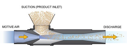
Pneumatic conveying involves moving of bulk material in a stream of various carrier gases in closed tubes (pipelines). Air mover supplies the specified volumetric flow rate of the free air maintaining the appropriate pressure in the conveying system. Air movers available for the pneumatic conveying system applications ranges from the fans and blowers producing high volumetric flow rates at relatively low flow rates and vice versa . A relatively high velocity is required and controlled by blower. Hence keeping the power requirement same the velocity of conveying medium i.e. air can be increased by implementing venturi feeder.
Venturi feeder consists of a short length of pipe shaped like a vena contracta, or the portion with the least cross-sectional area, which fits into a normal pipe-line. The hindrance caused to the flow of liquid at the throat of the venturi produces a local Pressure drop in the region that is proportional to the rate of discharge. The throat diameter is typically between 1/3 and ¾ of the inlet pipe diameter. Filtration unit is a gas solid separation device performs two functions. Firstly, it recovers conveyed material as much as possible for the next stage of handling or treatment process. Secondly, it minimizes the pollution of the working environment.
This zone is considered critical in pneumatic conveying system. (fig 6 &7) In this zone, the solids are introduced into the flowing gas stream. Initially, the solids are essentially at rest and a change in momentum occurs when solids are mixed with the flowing gas. Associated with this momentum change is the need to provide an acceleration zone. The acceleration zone consists of a horizontal pipe of certain length designed such that the solids are accelerated to some ‘steady’ flow state. The selection, design and operation of feeders for controlling the delivery of bulk solids into the pneumatic conveying line are critical.
The feeder and hopper bottom should be designed as an integral unit. There are a number of different feeders that can be considered for pneumatic conveying systems. The most common type of dilute phase systems is the rotary-vane feeder, sometimes called the rotary-air-lock feeder. The rotary feeder is the heart of a dilute phase system where an airlock feeder is needed. In many cases, a system that was almost inoperable has been put back on its feet by simply removing an improperly sized or wrong style of feeder and installing the right unit for the job.
Many designers try to skimp on the rotary feeders, but it is generally penny-wise and pound-foolish to do so because of the troubles that can develop with reduced system capacity, frequent plug-ups, and especially with subsequent high maintenance of misapplied feeders. Apart from conveying systems that utilize “blow pots” as a feeder, there is generally a pressure differential involved across the rotary vane feeder, either positive or negative. Under negative (vacuum) conditions the feed problems are usually minimal. However, under positive pressure conditions in the pipeline, a certain amount of the air will try to flow through the feeder in the opposite directions from the solids.
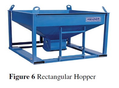
Most granular bulk solids are passing through silos, bins and hoppers prior to or after being conveyed. In some cases this process is repeated a few times. The basic requirement of a good storage bin is that it can store the required quantity of materials and that it can discharge this quantity safely and reliably by gravity. There are basically three flow patterns in bins. These are known as mass-flow, funnel-flow, and expanded-flow.
After doing all calculation & analysis it is conclude that high nozzle velocities are always require to convey the material having high densities like sand & cement. The implementation of venturi is necessary for balancing pressure & velocities in the pneumatic conveying system. The material feeding areas in conveying system have more importance to calculate the efficiency of the system. The theoretical & practical values of discharge are equal in range with standard values. Hence this system is efficient to use in any powder manufacturing industry or for the handling of plant ash.
Nilesh Bodkhe, Sanghshil L. Kanekar and Tushar G. Bhore
[1] L.P. Dhole, L.B. Bhuyar and G.K. Awari. Design Considerations for Pneumatic Conveying System, VSRD-TNTJ, 2(8), 2011, pp.382-389.
[2] D. Homa, H. Szlumczyk, K. Janerka Operation of Pneumatic Conveying Systems In Technological Processes,
[3] Vijay K Agarwal, Amit Suhane. Effect of Bend Geometry on Erosion and Product Degradation In Pneumatic Conveying Pipeline Systems
[4] S. R. Shah, S. Rastogi, O. Mathis. Applications of Dry Bottom Ash Removal & Transport for Utilization, Fly Ash India 2005, New Delhi.
