


Published on Apr 07, 2026
The smart home concept has constantly gained popularity over the past decades following the advent of technology. However, concerns on flexibility and infrastructure requirements discourage the widespread implementation of this concept. This project aims to improve the overall experience of a smart home by integrating the Wi-Fi IEEE 802.11 wireless communication standard into a standard smart home sensory network. The tasks of the project were centred on the development of a Wi-Fi integrated smart home system with a PIC® microcontroller and a Wi-Fi module as the core components. Additional components such as light-dependent resistor (LDR), temperature sensor, light-emitting diodes (LEDs) and DC motor were included to mimic a real life home environment.
A custom designed Android graphical user interface (GUI) application was also developed to enable automated and manual control of the modelled smart home. The final smart home prototype presented the integration of Wi-Fi into a smart home network that grants users with greater flexibility while preserving the existing smart home experience.
ades. The pioneering research in this area was conducted by the Massachusetts Institute of Technology (MIT) Media Lab, with the establishment of Smart Rooms. Since then, further research have been done to expand this concept into various applications. In general, a smart home establishes a home environment with ambient intelligence and automatic control. This is achieved by having a well-established network of sensors which constantly collects data of the home environment. The data will then be processed by computing devices such as computers or microcontrollers and appropriate appliance operations will be performed accordingly. The existing sensory networks in smart homes are constantly improving with the advent of technology, allowing more sensitive detections and faster responses. This allows smart homes to be targeted for more sophisticated tasks such as security needs, eldercare, healthcare, childcare, energy efficiency and improvement in quality of life. However, a few major downfalls still exist, limiting the smart home concept from spreading further.
The primary limitation of existing smart home systems lies within the necessity to establish a base station at a fixed location. This limitation is present as a transceiver unit should be attached to the base station for data transfer purposes. This caps user flexibility since smart home monitoring or control can only be done from a single spot in the home area. Not least, existing smart home sensory network requires excessive number of transceiver nodes to fully actuate the system. For instance, the simplest smart home network requires a minimum of two transceiver nodes (a pair) to complete the sensor network. One transceiver node is attached to the base station, while the other is directly connected to sensors or output devices.
When the smart home scale increases, the number of transceivers would increase proportionally. Hence, this project aims to tackle the above limitations from a single approach: through the integration of the Wi-Fi IEEE 802.11 communication standard into existing smart home network. This solution was opted since Wi-Fi infrastructures are continuously growing in popularity and readily available in a majority of households [9]. In addition, an Android GUI application was developed to interact with the proposed Wi-Fi integrated smart home system. These implementations were targeted at altering the means in which users interact with the smart home environment, granting a higher degree of flexibility in smart home management.
The developed smart home system involved the integration of the Wi-Fi communication standard into a typical smart home sensory network. This integration enabled Internet Protocol (IP)-based wireless monitoring and control of household sensors and appliances. This Wi-Fi integrated smart home system used a PIC® microcontroller and a Wi-Fi module for integration purposes. In order to demonstrate a real life smart home environment during prototyping, a LDR and a temperature sensor were included as input devices to monitor light intensity and temperature respectively.
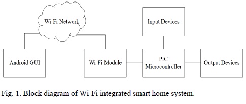
Meanwhile, LEDs and DC motor were selected as output devices which represent real life lightings and fan. Furthermore, an Android GUI application was developed to allow remote monitoring and control of smart home from handheld devices. C language was used to develop the software for the microcontroller-based smart home system, whereas Visual Basic language was used to develop the Android GUI application. Fig. 1 shows the block diagram that provides an overview of the Wi-Fi integrated smart home system.
into a smart home network. In this project, the XBee Wi-Fi module by Digi International® Inc. was utilized [10]. An XBee starter kit was included to aid the configuration of the XBee Wi-Fi module. The XBee Wi-Fi module was configured to enable the establishment of a Wi-Fi direct connection. The XCTU software [11] by Digi International® Inc. was used to configure several serial interfacing settings, network settings and addressing settings of the XBee Wi-Fi module. Among these parameters, the crucial ones would be setting the baud rate to 9600 bits per second (bps). Besides, the network infrastructure mode was selected as Soft AP mode (Wi-Fi direct). Not least, the IP protocol was chosen as the Transmission Control Protocol (TCP) and the IP address as well as port number were assigned.
The PIC® microcontroller was the brain of the Wi-Fi integrated smart home system. The PIC® microcontroller used in this project was the PIC18F4550 microcontroller from Microchip Technology Inc. [12]. The 40-pin PIC18F4550 microcontroller was selected as it inherits all the advantages of the PIC18 microcontroller series and meets the project requirement which demanded high performance at low power consumption [12]. The microcontroller was interfaced with the Wi-Fi module as well as input and output devices. Programming of the PIC18F4550 microcontroller was done using the mikroC Pro software by ©MikroElektronica [13] in C language. The interfacing of PIC® microcontroller and XBee Wi-Fi module involved the establishment of a Universal Asynchronous Receiver/Transmitter (UART) communication. In terms of hardware connection, the UART pins of both the microcontroller and Wi-Fi module were of interest. First, the VDD and GND pins of both hardware were directly connected. Next, the RX and TX pins of both hardware were cross connected, i.e. TX pin of the microcontroller was connected to RX pin of the Wi-Fi module and vice versa. In terms of software coding, the UART library in mikroC Pro was utilized. UART communication was initialized at 9600 bps using the command:
UART1_Init(9600);
Upon UART initialization, data transmission and reception with the XBee Wi-Fi module were done with the following commands:
UART1_Write
UART1_Write_Text
UART1_Data_Ready
UART1_Read
In addition, the PIC® microcontroller was interfaced with input devices, which were sensors utilized to monitor light intensity and temperature. A LDR [14] was used to detect light intensity, while a LM35 temperature sensor [15] was used to measure the surrounding temperature. In terms of hardware, the output of the LDR was connected to the RA1 pin of the microcontroller, while the output of the LM35 sensor was connected to the RA2 pin of the microcontroller. The analogue voltage values from these sensors were extracted using the mikroC code
ADC_Read
The extracted values then underwent measurement scaling to obtain the actual values. Actual light intensity values were obtained through the scaling formula:
light intensity=(ADC value×5)/1024
Meanwhile, actual temperature values were scaled by referring to real life temperature readings from AccuWeather.com’s RealFeel® Temperature [16].The scaling formula was:
temperature=(ADC value-20)/2
Lastly, the PIC® microcontroller was interfaced with output devices, which were the electronic components representing household appliances. In this project, LEDs represented lightings, while a DC motor represented a ceiling fan. The LEDs were easily turned on and off by toggling the output pins. On the other hand, DC motor interfacing involved speed variation through pulse width modulation (PWM). An additional L293D integrated circuit [17] was bundled with the DC motor and connected to the RC2 pin of the microcontroller to enable PWM control. From the software aspect, PWM was initialized at the minimum motor driving frequency of 2 kHz and started with the commands:
PWM1_Init(2000);
PWM1_Start();
Speed variations were next achieved by varying the DC motor duty cycle through the command:
PWM1_Set_Duty
In this project, an Android GUI application was developed to allow remote monitoring and control of the smart home. The GUI application was a client application connected to the host XBee Wi-Fi module via a Wi-Fi direct connection. The Android GUI application in this prototype was written with the B4A software [18] in Visual Basic language. The development of the Android GUI application followed the guidelines
1) The Network and RandomAccessFile libraries in B4A were required for coding.
2) A TCP socket was created and initialized to establish a TCP connection.
3) The host was connected at the specific IP address and port number using the command Socket.Connect.
4) Data was read from the host using the command Socket.InputStream.
5) Data was written to the host using the command Socket.OutputStream.
6) Input and output streams were treated as asynchronous data streams (AsyncStreams).
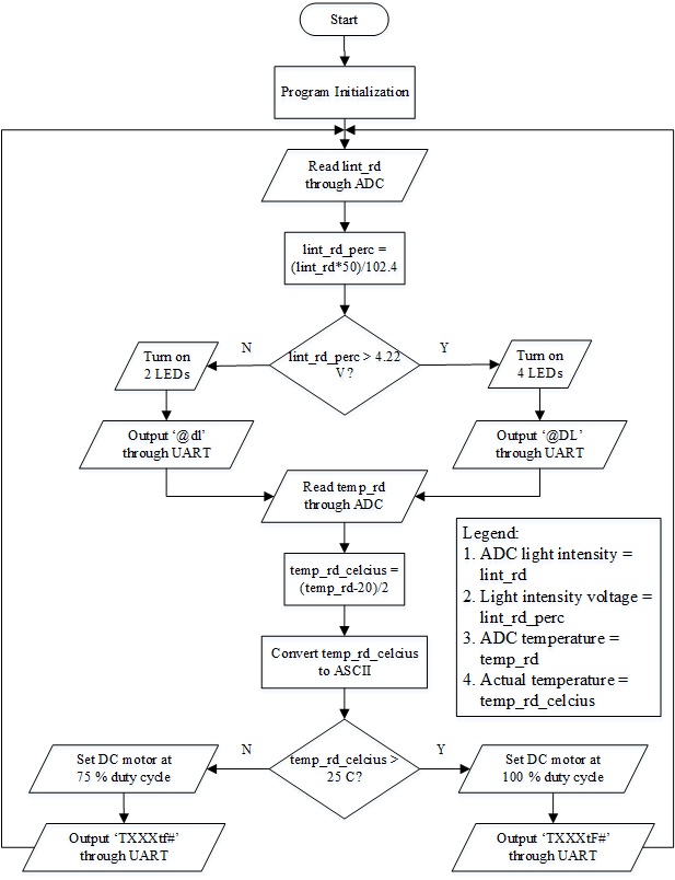
The Wi-Fi integrated smart home system in this project was developed with two separate schemes of automated control and manual control. Fig. 2 illustrates the flow chart of the automated control section of the smart home system. During automated control, the LDR was tasked to monitor surrounding light intensity and the LM35 temperature sensor was tasked to monitor surrounding temperature. The collected luminance and temperature values were compared with predefined set points. Appropriate appliance manipulations were then carried out by toggling the LEDs and DC motor.
At the same time, the status of all input and output devices were delivered via UART to the XBee Wi-Fi module for monitoring on the Android GUI application. Fig. 3 illustrates the flow chart of the manual control section of the smart home system. The manual control of smart home was handled by the RX peripheral interrupt.
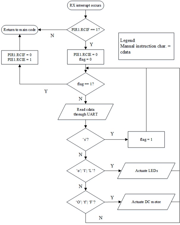
When the Android GUI application delivered a manual control request to the RX pin of the microcontroller via the XBee Wi- Fi module, the peripheral interrupt will be triggered. In this interrupt loop, character checking will be performed. When a predefined character was received, the corresponding manual control operation will be carried out. The interrupt loop will be exited upon receiving an exit flag and the smart home system will return to automated control.
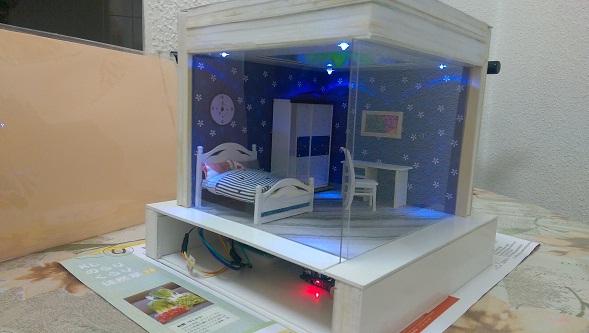
The developed Wi-Fi integrated smart home system was presented in the form of a smart room model, fully furnished and wired as illustrated in Fig. 4. The PIC® microcontroller, Wi-Fi module and PCB circuitry were placed at the lower circuitry compartment of the smart room model. Meanwhile, the upper showcase compartment hosted the LDR, temperature sensor, LEDs and DC motor which were concealed in the furniture. Fig. 5 illustrates the developed Android GUI application. The GUI application comprised of three screens. Fig. 5(a) illustrates the main screen which required users to provide the IP address and port number to establish a Wi-Fi connection. Upon connection, users were led to the automated control screen in Fig. 5(b) where smart home status were monitored. The manual control screen that enabled users to manually control appliances is shown in Fig. 5(c).
The smart room model was operated with the developed Wi-Fi integrated smart home system. In general, two smart home control schemes were involved, namely the automated control scheme and the manual control scheme. In the automated control scheme, surrounding light intensity and temperature were monitored through the LDR and temperature sensors respectively. By comparing the luminance and temperature values with predefined set points, the LEDs and DC motor were manipulated accordingly. The status of all input and output devices were delivered to the Android GUI application at the same time.
In this project, the Wi-Fi IEEE 802.11 wireless communication standard was successfully integrated into a smart home sensory network using the PIC18F4550 microcontroller and the XBee Wi-Fi module. The resulting smart room model prototype has IP-based wireless monitoring and control capabilities via Wi-Fi. The prototype was configured with a simple smart home scheme that consisted of both automated and manual control. In addition, an Android GUI application was developed. This client application allowed the monitoring of sensor and output device status during automated control.
The manual control operations were also performed through this application. The management of smart home related activities from handheld devices promotes a higher degree of flexibility among smart home users. As an added value, the two-directional flow of data between the connected client and the smart home system was achieved through a single XBee Wi-Fi transceiver module only. This has widely created the opportunity to reduce the number of infrastructure nodes in a smart home sensory network.
[1] L.C.D. Silva, C. Morikawa and I.M. Petra. “State of the art of smart homes.” Engineering Applications of Artificial Intelligence, vol. 25, pp. 1313-1321, 2012.
[2] M. Chan, D. Esteve, C. Escriba and E. Campo. “A review of smart homes – Present state and future challenges.” in Computer Methods and Programs in Biomedicine, vol. 91, pp. 55 – 81, 2008.
[3] H.C.C. Tan, L.C. De Silva. “Human Activity Recognition by Head Movement using Elman Network and Neuro-Markovian Hybrids.” Proceedings of Image and Vision Computing New Zealand, pp. 320-326, 2003.
[4] L.C. De Silva. “Audiovisual emotion recognition.” IEEE International Conference on Systems, Man and Cybernetics, 2004.
[5] R. Cai, L. Lu, A. Hanjalic. “Unsupervised content discovery in composite audio.” Proceedings of 13th Annual ACM International Conference on Multimedia, pp. 628-637, 2005.
