

Published on Apr 07, 2026
Articulated Wheeled Vehicles (AWVs) are a class of wheeled locomotion systems where the chassis is connected to a set of ground-contact wheels via actively- or passively-controlled articulations, which can regulate wheel placement with respect to chassis during locomotion. In this paper the design, development and integration of vibration isolated mobile trailer platform, customized to meet the user’s requirements in general and optical requirements in particular is discussed.
The study also focusses on performance requirements, system requirements and technical details of the articulated vehicle system.
An articulated vehicle is a large vehicle made in two separate sections, a tractor and a trailer, connected by a pivoted bar. These vehicles can cary heavy loads and can take sharp turns. An articulated truck is a vehicle that is most commonly used in construction work. Articulated trucks are used to haul heavy loads, sometimes over difficult terrain, and they can be considered a type of tractor-trailer unit. The main feature of an articulated truck that puts it in a separate driving class is its drive system. The drive system is based on the number of wheels on the axles used to pull the truck [1]. The most common system is the 6 x 6 system, in which the truck has six wheels on three axles and all are used when driving the truck.
Another system used is the 6 x 4 drive, in which only the rear four wheels are used when driving. The original drive system in articulated trucks is the famous 4 x 4 drive. This was designed for trucks that drive over the roughest terrain on the planet [2]. The 4 x 4 drive system helps the truck maneuver over terrain that could be a potential problem for the goods being carried. Wheeled Mobile Platforms/Vehicles comprise of a platform supported by multiple wheels which allow for relative motions between the platform and the ground. Wheeled vehicles have traditionally offered simplicity of mechanical construction and control, very favorable payload-toweight ratio, excellent load and tractive-force distribution, enhanced stability and energy-efficiency, making them the architecture of choice for most man-made terrestrial locomotion systems
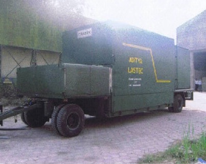
Following section discusses the design and development of a mobile trailer platform undertaken at DRDO for military applications. Sub-system of mobile trailor platform: The complete system of mobile trailer platform consists of the following sub-systems;
Well bed full-trailer with Air Bag Suspension
Auto Leveling System
EMI shielded A/C control room
3 Axes alignment system
Metallic Sliding Canopy
Vibration Isolation System
Nitrogen Gas Purging System
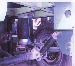
Well bed full trailer wit airbag suspension: Fig. 1 shows a well bed full-trailer with air bag suspension. It has a payload capacity of 8 tons. Depending on the load the overall trailer frame length and width will be approximately 10000mm and 3000mm respectively. The pressure in the airbag is 15-20psi when loaded or when towing. Air bag suspension on both axes should be capable to reduce the vibration during transportation by normal road/rough road to less than 0.75 g and impulse of 5 g at the speed of 60 km/hr on plain road and 30km/hr on rough road.
Input shock level at axle will be from 5 to 10 g. The air should be tapped from the trailer brake circuit with suitable pressure protection valve and air reservoir. One disadvantage of airbags is that they limit wheel travel because they can only flex so far since they are attached to both the frame at the top and axle at the bottom. Provision is made to mount four Nitrogen Cylinders at the front deck with suitable clamping facility. Further, a floor sheet is provided to make the well bed dust proof. Provisions are also made to mount other accessories like ladder, tool box etc.
Welded structure shall be fabricated from Sailma Steel-350 (Specifications-Yield Strength 350Mpa and Ultimate Tensile Strength 610Mpa). The trailer structure shall be optimally designed to withstand loading pattern, minimum vibration during operation and transportation, meeting leveling accuracies and to suite mounting of 3 axes alignment system. Trailer brakes are actuated from tractor. Twin line air brake system is coupled to tractor brake system through palm coupling. Pressure protection valve is to be provided in the circuit. Fail safe automatic braking and mechanical parking brakes are to be provided. The pneumatic lines from Air bag suspension and anti-vibration air mounts charging shall be tapped from brake system through an air reservoir.
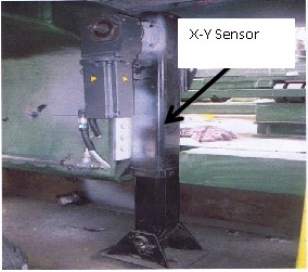
Auto-Leveling System: Auto leveling system is used to check and monitor the land irregularity. It has got two sensors to level the vehicle in longitudinal direction called X-sensor and in transverse direction called Y-sensor. These sensors will sense the irregularities on the land and send a signal to the four mechanical actuators. Each mechanical actuator is driven by a servomotor. The actuation is further amplified by the amplifier and sends to controller. The controller is connected to the computer through data acquisition system which will acquire the data, convert it in to digital signal and display on the monitor.
The land irregularities are red in minutes. The accuracy of the measuring instrument is limited to ±5 min in longitudinal direction and ± 2 min in transverse direction. The trailer shall be provided with PLC based Auto-Leveling System to level the trailer platform within accuracy as per required. Four electrically actuated mechanical jacks to be provided. The mounting bracket surface shall be machined and leveled with trailer chassis frame and auto level clino-meter mounting surface plate. The boring in jack mounting bracket shall be exactly vertical. The other sub-assembly of auto leveling like power amplifier, connectors and cable-harness shall be mounted suitable.
EMI shielded Air conditioned control room: The control room is shielded from electromagnetic radiations to protect it from th laser system. There are many methods available for making an enclosure shielded against EMI/RFI. To produce a Faraday Cage, you need a metal enclosure, which will absorb/reflect the Electromagnetic energy. Nonmagnetic metals, such as aluminum will not work at very low frequencies; a magnetic material; for example, Iron or Nickel is required. At high frequencies, the conductivity of the material dictates its effectiveness.
Conductive Plastic is the best solution for some styles of plastic enclosures. The plastic is compounded with stainless steel fibers, forming a 3 dimensional conductive matrix inside the base material. This method provides a consistent enclosure, with no secondary coating quality issues. 3 Axes alignment system: A platform to support 2ton load and to provide movements X axis- 150mm(±100mm) , Z axis-100mm(±50mm) and yaw ±5 degrees to facilitate alignment with another system. It consists of a laser system to align two components in all the three directions. The alignment accuracy of the system is ±0.5mm for linear alignment and ±0.5deg for rotational alignment.
This canopy is used to enclose equipment in trailer well bed. It is a dust proof, waterproof sliding canopy made of galvanised iron. The canopy for the present system is designed for the following specifications. The structural, members, foldable rails, front and rear panels shall be integrated with the trailer.
Ground Clearance-350mm
-- Ramp Angle-6deg
-- TCD (along with suitable tractor)-<25m±1
-- Max speed-40 to 50 km/hr plain road and 30km/hr on Rough roads
-- Temperature- 10 to 55 deg C (operation)
-- Humidity-Humid < Salt, dusty condition
-- Wind speed-108km/hr for survival and 72km/hr for operation
-- Vibrations-1.5g during transportation
Sufficient number of vibration air mounts on the top of 3 axes alignment system to support the optical equipment of average payload 1900 kg.
Four Nitrogen Cylinders as per specifications are provided on the front deck with suitable clamping. It is used to create an inert atmosphere. Moisture has a damaging effect on the integrity and performance of electro-optical equipment and other sealed enclosures, corroding electronics and condensing on optical surfaces. Dry gas purging is frequently used to create very low dew points within sensitive equipment
A study is made on the articulated vehicle system to explore the accessories such as auto levelling system, 3-axis alignment system, and vibration isolation system etc., required for the testing of various parts of an articulated vehicle.
[1] Jianjun Dong, Wenming Zhang, Boqiang Shi. General of Underground Mining Articulated Dump Truck and Market in China. Coal Mine Machinery, vol.28, no.12, pp.1-3, 2007.
[2] Jinyue Tian, Huixing Jia. Dynamic Simulation of the Overturning of Articulated Vehicles. Transactions of the Chinese Society for Agricultural Machinery, vol.37, no.7, pp.26-29, 2006.
[3] Meirong Zhao, Kai Chang, Xi Yang. Analysis of the Steering Feature for Mine Articulated Vehicles. Mechanical Engineering & Automation, no.4, pp.100-104, 2009.
[4] Jianchun Wang. Dynamical mathematical model of in situ steering of articulated vehicles. Construction Machinery, no.6, pp.86-90, 2008.
[5] Minzhen Ye. Study of steering Procedure of Articulated Frame and Design of Steering System. Construction Machinery, no.11, pp.9-11, 1997.
